Model 742, Main outputs – Studio Technologies 742 2005 User Manual
Page 12
Issue 2, May 2005
Model 742 User Guide
Page 12
Studio Technologies, Inc.
Model 742
signals can also be connected. In this
case, pin 2 is connected to signal high (+
or hot), and pins 1 and 3 are connected to
shield. If this results in hum or other noise
being present, try connecting pin 2 to
signal high and shield to pin 3; leave pin 1
unconnected (“floating”). To provide maxi-
mum flexibility, it is recommended that
the signals connected to the line inputs
be wired by way of points on an audio
patch bay.
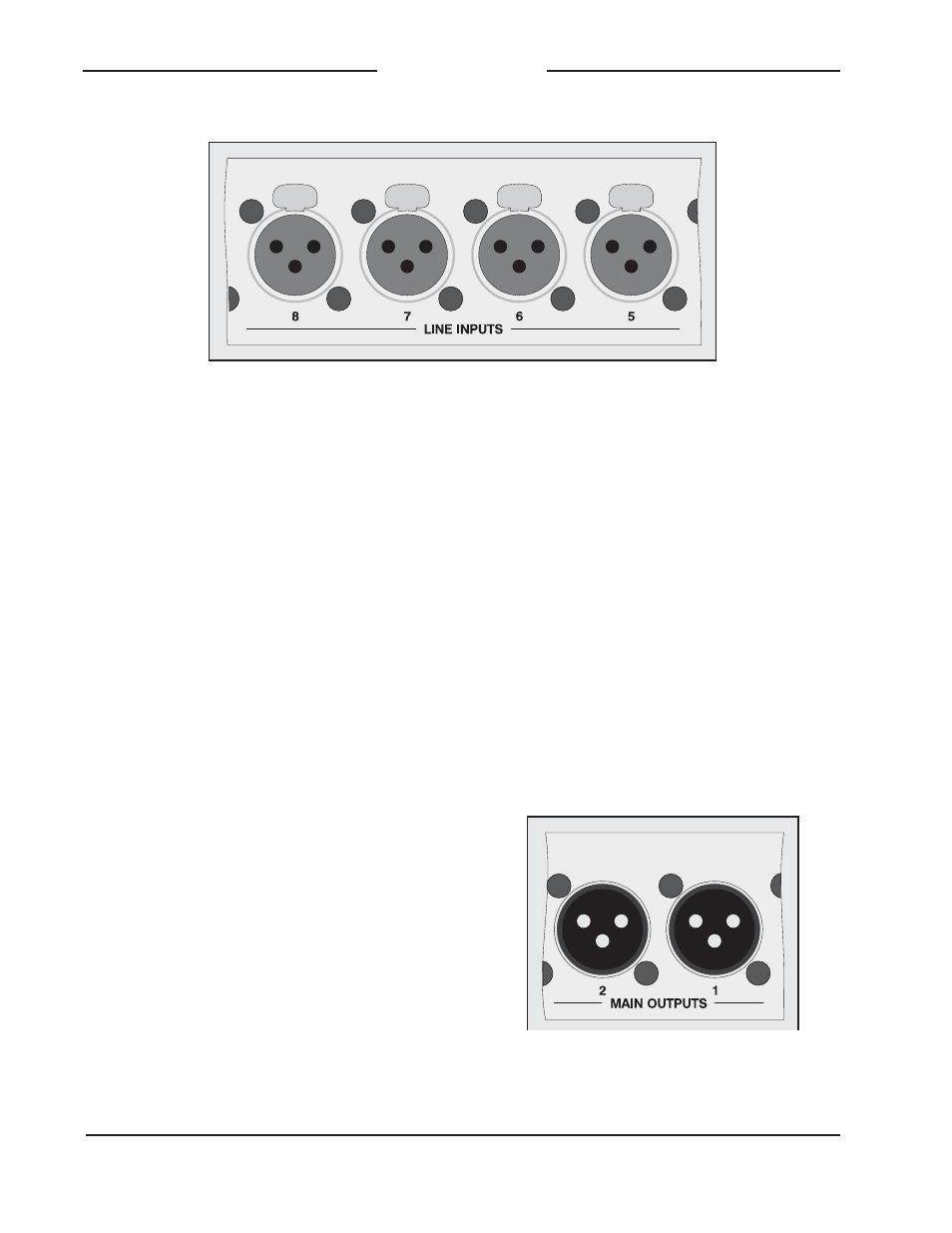
Main Outputs
The Model 742 contains two main outputs
which are directly associated with output
buses 1 and 2. They are electronically
balanced, capacitor coupled, with a nomi-
nal level of +4 dBu. The output circuitry
is capable of driving balanced or unbal-
anced loads of 600 ohms or greater. Note,
however, that as the load impedance ap-
proaches 600 ohms the output levels will
drop slightly. A 0.5 dB difference in output
level can be expected as the load imped-
ance changes from 10 k ohms to 600
ohms. This loading situation applies to the
monitor outputs and reference tone direct
outputs as well.
Note that the main outputs are intended
only for connection to devices located
within a broadcast vehicle or dedicated in-
door facility. While the circuitry used in the
outputs is robust and sonically excellent,
they’re not intended for direct exposure to
the extreme conditions that can occur in
the nasty “outside world.” This limitation is
normally not an issue as the main outputs
will typically be connected to inputs on
a distribution amplifier. Should the main
outputs need to be connected directly to
a vehicle’s I/O panel, it’s recommended
that one-to-one isolation transformers be
placed in their signal paths. Ensure that
any transformer selected is specified for
use in line-level applications.
Detail of back panel showing main
output connectors
Detail of back panel showing line input connectors