Introduction – Studio Technologies 92 User Manual
Page 5
Model 92 User Guide
Issue 1, December 2006
Studio Technologies, Inc.
Page 5
Introduction
The Model 92 is designed to test the integrity
of DT12-type cable assemblies. Widely used
by the mobile broadcast industry, “DT12s”
provide twelve balanced signal pairs, each
with an individual shield. For on-air broadcast
applications it’s critical that all signal paths
are fully functional. But without specialized
test equipment it’s impossible to confirm
DT12 performance. The Model 92 accom-
plishes this task in a simple-to-use but techni-
cally sophisticated manner—it’s far from just
a continuity checker. Under software control,
the internal microcontroller-based circuitry
independently tests each signal pin for con-
nectivity, opens, and shorts. The Model 92
can ensure that the value of a television
production trailer’s significant investment in
DT12 cable assemblies is maximized. When
two Model 92 units are used together they
can prove invaluable for facilities that include
permanently installed DT12 cabling.
For operator convenience, testing can be
selected from among two formats: chan-
nel mode or pin mode. Channel mode is
provided specifically for field applications
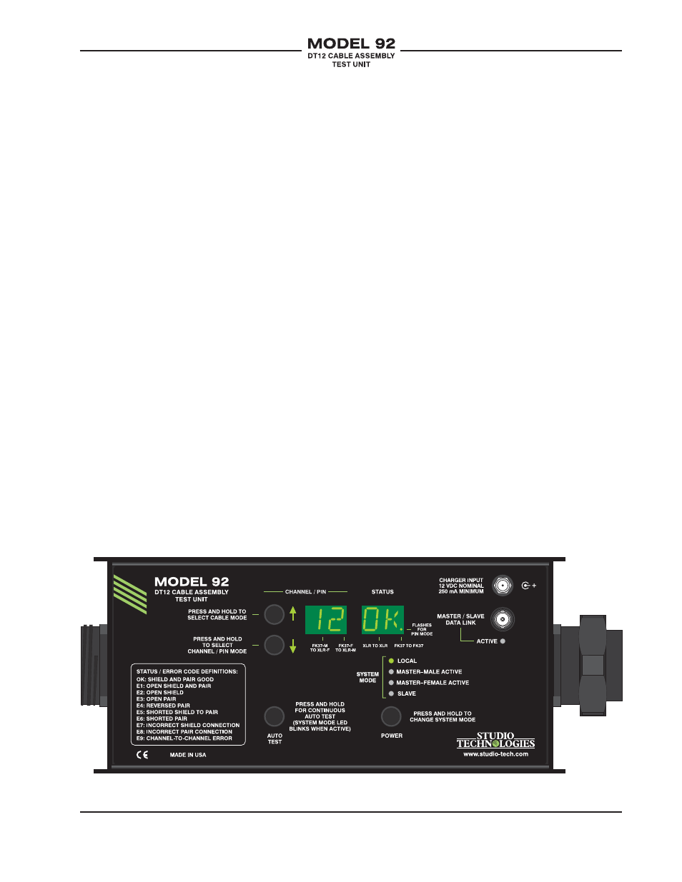
Figure 1. Model 92 Top View
where testing is most effective when ori-
ented toward how a DT12 is actually used.
Pin mode is oriented toward supporting
technical personnel who are responsible for
fabricating or repairing cable assemblies.
In both modes solid-state displays indi-
cate which channel or pin is being tested,
along with the test result. For ease of use
the Model 92 supports both automatic and
manual testing. The unit is housed in a rug-
ged aluminum enclosure and is constructed
for reliable “field” performance where abuse
is often a way of life. An internal recharge-
able battery provides the operating power.
When the Model 92’s channel mode is
selected, testing is organized as twelve
signal channels. Two of the display digits
indicate which channel is currently being
tested. The display digits, depending on
which mode is selected, can also display
the test results. The results can include ALL
OK and FAIL, as well as a number of error
codes. The codes allow conditions such as
open shields or pins, crossed signal pairs,
or short circuits to be displayed. In the pin
test mode, all 37 pins associated with the