Channel/pin mode – Studio Technologies 92 User Manual
Page 12
Issue 1, December 2006
Model 92 User Guide
Page 12
Studio Technologies, Inc.
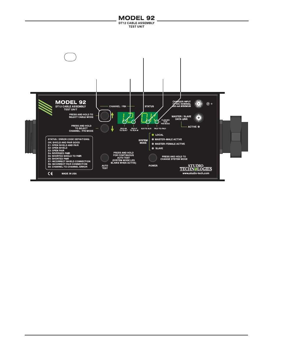
Channel/Pin Mode
The Model 92 offers two basic ways of test-
ing cable assemblies: channel mode
or pin mode. Refer to Figure 5 for details.
The channel mode is available for use in
all four of the cable modes: FK37 to FK37,
FK37-M to XLR-F, FK37-F to XLR-M, and
XLR to XLR. Channel mode is generally
appropriate for rapid field testing of exist-
ing inventory of DT12 and XLR cables. Pin
mode is only available in the FK37 to FK37
and XLR to XLR cable modes. It is not of-
fered with the other two cable modes as it’s
not appropriate for use with DT12 “fanouts.”
In the channel mode DT12 testing is orga-
nized as twelve 3-conductor groups. The
3-conductors consist of a shield and a sig-
nal pair. In standard DT12 cable assemblies
these twelve channels are wired using pins
1 though 36 of FK37 connectors; pin 37 is
generally not used.
The pin mode is provided so that a detailed
view of the signal paths associated with a
cable assembly can be obtained. In the pin
mode testing can be performed on all 37
pins of a FK37 connector associated with a
DT12 assembly, although typically only pins
1 through 36 are utilized. Pin mode is useful
when fabricating new DT12 assemblies or
repairing cable assemblies which the chan-
nel mode has identified as being defective.
The button located to the left of the down
arrow is used to select between channel
mode and pin mode. Pressing and holding
this button for two seconds will cause the
mode to change between channel mode
Fanout:
FK37 male
to XLR female
Figure 4. Model 92 Configuration—Cable Modes
Fanout:
FK37 female
to XLR male
XLR to XLR
FK37 to FK37
Press and hold
“up” button to
cycle through
cable modes.