Operating modes – Studio Technologies 220 2008 User Manual
Page 19
Model 220 User Guide
Issue 4, October 2008
Studio Technologies, Inc.
Page 19
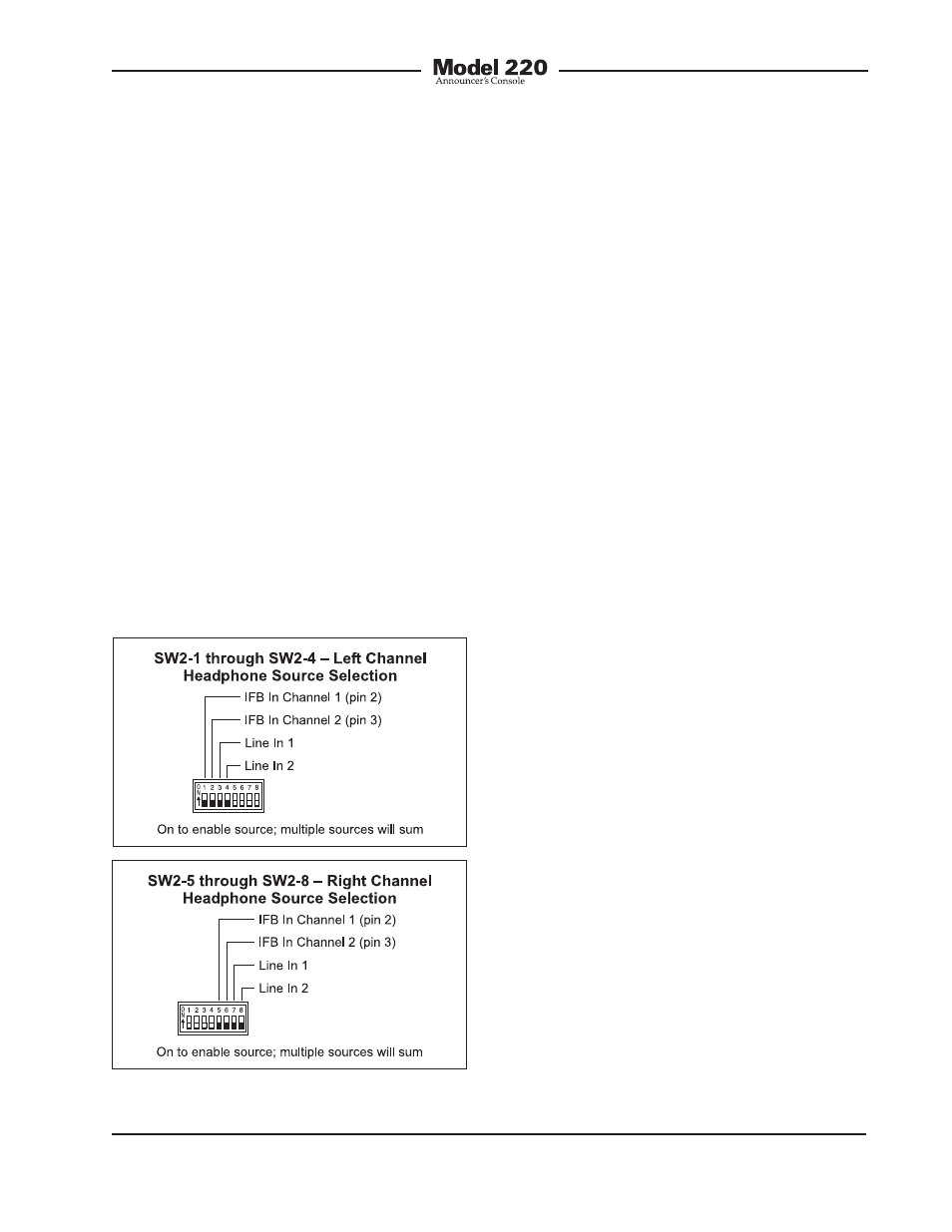
the left and right channels. This would
entail setting switches SW2-2 and SW2-6
to their on positions. All other switches
would remain in their off positions.
A more complex application might have
a 2-channel IFB circuit connected to the
Model 220. In addition, a line-level audio
signal from a golf event “spotter” is con-
nected to line input 1. In a case such as
this, it would be typical for IFB channel 1
to be assigned to the headphone’s left
channel, IFB channel 2 assigned to the
right channel, and line input 1 also as-
signed to the right channel. This would
allow both IFB channel 2 and “spotter”
audio to be heard in the headphone’s
right-channel output. To achieve this
would require that switches SW2-1,
SW2-6, and SW2-7 be placed in their
on positions. Note that using another
announcer console unit from Studio
Technologies at the “spotter” location
could also prove effective. It would provide
all the necessary microphone preamplifier,
talkback routing, and headphone monitor-
ing resources.
Note that in some cases a user may wish
to wear a headset or a pair of headphones
in a left/right orientation opposite of what’s
usual. In this situation the transducer
designated for the left ear would actually
supply audio to the user’s right ear, and
vice versa. A specific application where
this occurs is where on-air talent needs to
have a headset’s boom microphone come
across the right side of their face, rather
than the more-typical left side. In this case
it’s important to select the left- and right-
channel headphone source assignment
accordingly. With the Model 220’s flexible
source selection there’s no reason why
users, such as on-air talent, shouldn’t
have their cue sources assigned correctly.
There may be cases where a monaural
“single-muff” headset or headphone will
be connected to the Model 220’s head-
phone output. In this case the desired
source(s) should be routed only to the left
channel. No sources should be assigned
to the right channel. This will eliminate the
short-circuit current that could occur when
a 2-conductor (monaural) plug is mated
with the Model 220’s 3-conductor (stereo)
headphone output jack.
Operating Modes
The sixteen switches associated with
switch assemblies SW3 and SW4 are
used to configure the Model 220’s operat-
ing modes. Technically, these switches
“talk” to the microcontroller integrated
circuit and associated software that give
the Model 220 its “smarts.” The software
has been carefully designed to provide
Figure 6. Left and right channel headphone
source selection settings