Configuration – Studio Technologies 220 2008 User Manual
Page 16
Issue 4, October 2008
Model 220 User Guide
Page 16
Studio Technologies, Inc.
were created at the factory using a stan-
dard personal computer graphics program
and laser printed onto 3M CG3300 trans-
parency film. The desired button labels
can be cut out with a pair of scissors, fol-
lowing the printed guide lines that indicate
the required size.
The clear lens on top of each button cap
can be removed with a fingernail or small
screwdriver. Be certain not to scratch the
button if a screwdriver or other small tool
is used. The clear label can be removed
and replaced. The button cap is then
snapped back into the top of the button
housing using finger-pressure only. No
tool is required to replace the button cap.
If you need to make your own labels the
process is quite simple. Use a personal
computer to create the desired text. The
finished label size should be 0.625-inches
(15.8 mm) square. The completed artwork
can then be printed on transparency film
sheets using a laser or inkjet printer. These
sheets are readily available from most of-
fice supply stores. A pair of scissors or an
X-ACTO® knife will complete the task.
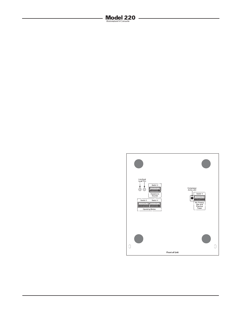
Configuration
For the Model 220 to support the needs
of specific applications a number of op-
erating parameters must be configured.
These include microphone preamplifier
gain, phantom power on/off, headphone
source selection, and operating modes.
Four 8-position DIP-type switch assem-
blies are used to establish the desired
configuration. These switch assemblies
are referred to as SW1 through SW4, with
individual switches designated as SW1-1,
SW1-2, etc. The switch assemblies are ac-
cessed through openings in the bottom of
the Model 220’s enclosure. The enclosure
does not have to be disassembled
to gain access to the switches.
To prevent unauthorized personnel from
changing the configuration settings, a
security plate is attached to the bottom
of the Model 220’s enclosure. For conve-
nience, attached to the security plate is
a configuration settings label. It provides
a summary of the configurable parameters
and related information. Refer to Ap-
pendix A for a representative view of the
label. The security plate is held in place by
means of four rubber bumpers (“feet”) that
have built-in screws. Using your fingers,
remove the four bumpers so that the plate
can be removed. Refer to Figure 3 for a
detailed view of the configuration switch
assemblies.
Figure 3. Bottom view of Model 220 showing
configuration switches, trim pots, and
compressor active LED