Headphone source selection – Studio Technologies 220 2008 User Manual
Page 18
Issue 4, October 2008
Model 220 User Guide
Page 18
Studio Technologies, Inc.
doesn’t necessarily indicate that the main
output’s signal is being compressed. Un-
less specifically configured to do other-
wise, the output of the compressor is only
used for the talkback outputs.
It’s expected that the 20 and 60 dB gain
settings will not often be used. But there
are always exceptions and that’s why
they were included. It’s possible that
with a very “hot” microphone, such as a
phantom-powered condenser-type, 20 dB
of gain could be correct. It’s also possible
that a microphone with a very low-level
output, such as a ribbon-type, would need
60 dB of gain. But in general, the 30, 40,
and 50 dB gain settings will serve most
applications.
Note that if no gain switch is set to its
active (on) position the preamplifier will
operate at unity (0 dB) gain. In this mode
the preamplifier remains stable, but is
intended for use only during factory test-
ing. A valid exception would be where a
line-level signal is connected to the mi-
crophone input. This could occur with a
special Model 220 application. But with
a microphone connected as the input
source, one should never use the 0 dB
setting. The issue is that with no gain
added to the microphone input signal, the
relative noise floor on the main and talk-
back outputs will be much too high. These
outputs are designed for handling line-
level signals, expecting to receive the out-
put of the mic preamplifier. In conclusion,
the 0 dB gain setting doesn’t highlight a
problem, but simply reflects the unit’s
gain structure.
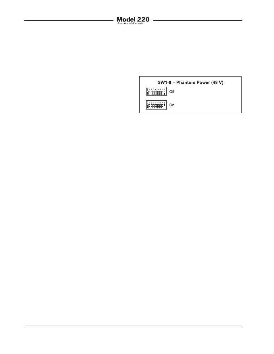
Phantom Power On/Off
The Model 220 can provide 48 volt phan-
tom power to the microphone input.
Switch SW1-8 controls whether or not
phantom power is active. By phantom
power’s very nature it could be left applied
to the microphone input at all times. But
generally people prefer to turn it off unless
required for a specific microphone.
Figure 5. Phantom power switch settings
Headphone Source Selection
Switch assembly SW2 is used to config-
ure the source or sources that are routed
to the stereo headphone output. The
headphone sources are IFB channel 1,
IFB channel 2, line input 1, and line input
2. The IFB channels are provided by way
of the IFB input connector located on the
Model 220’s back panel. The line inputs
are connected by way of two connectors
also located on the back panel. Associ-
ated with line inputs 1 and 2 are level trim
potentiometers. They are provided so
that audio sources with a wide range of
nominal levels can be effectively used as
cue sources. Please refer to the Advanced
Operation section of this user guide for
details on using the trim pots.
Each of the available input sources can
be assigned to the headphone output’s
left channel, right channel, or both the
left and right channels. The Model 220’s
circuitry allows any combination of input
assignments to be made. For example,
consider the situation where a single-
channel IFB system, with both program
and interrupt audio on pin 3, is connected
to the Model 220. In this case it may be
desirable to assign this IFB signal to both