Studio Technologies M212-00151 User Manual
Page 21
Model 212 User Guide
Issue 2, June 2006
Studio Technologies, Inc.
Page 22
people refer to this generically as an “AES”
digital audio signal. But this is confusing
and inaccurate as there are separate stan-
dards for 75 ohm unbalanced (AES3id)
and 110 ohm balanced (AES) digital audio
signals. (While the standards are separate,
both share the same method of formatting
the digital audio and control signals.)
The bidirectional digital interface is a
special type of 75 ohm unbalanced signal
that carries two channels of digital audio
in each direction. To clarify, over a single
unbalanced cable two channels of digital
audio are sent in one direction and two
channels of digital audio are sent in the
other. The bidirectional digital interface
uses a BNC connector which is located on
the Model 212’s back panel. The interface
is only appropriate for use in carefully en-
gineered systems that are compatible with
this type of signal. An example application
is where a Model 212 is directly interfaced
with a 75 ohm port on a Riedel digital
matrix intercom system.
AES3 input circuitry is located inside the
Model 212’s enclosure and is compatible
with balanced 110 ohm digital audio
signals. This type of signal is typically
found in non-broadcast applications
where the use of twisted pair wiring with
a maximum interconnection length of 100
meters does not pose a problem. The
Model 212 provides AES3 input circuitry
for installer-selected applications where
the desired connector is mounted into one
of the spare connector locations on the
Model 212’s back panel. Many applica-
tions use standard 3-pin female XLR-type
connectors for AES3 inputs. However, us-
ing other connector types, such as Neutrik
EtherCon, can be a convenient way of
transporting a number of different signals
over “CAT5” or “CAT6” twisted-pair cable.
is important. This could occur when the
connected headset or headphones are at
times placed on a desk or tabletop.
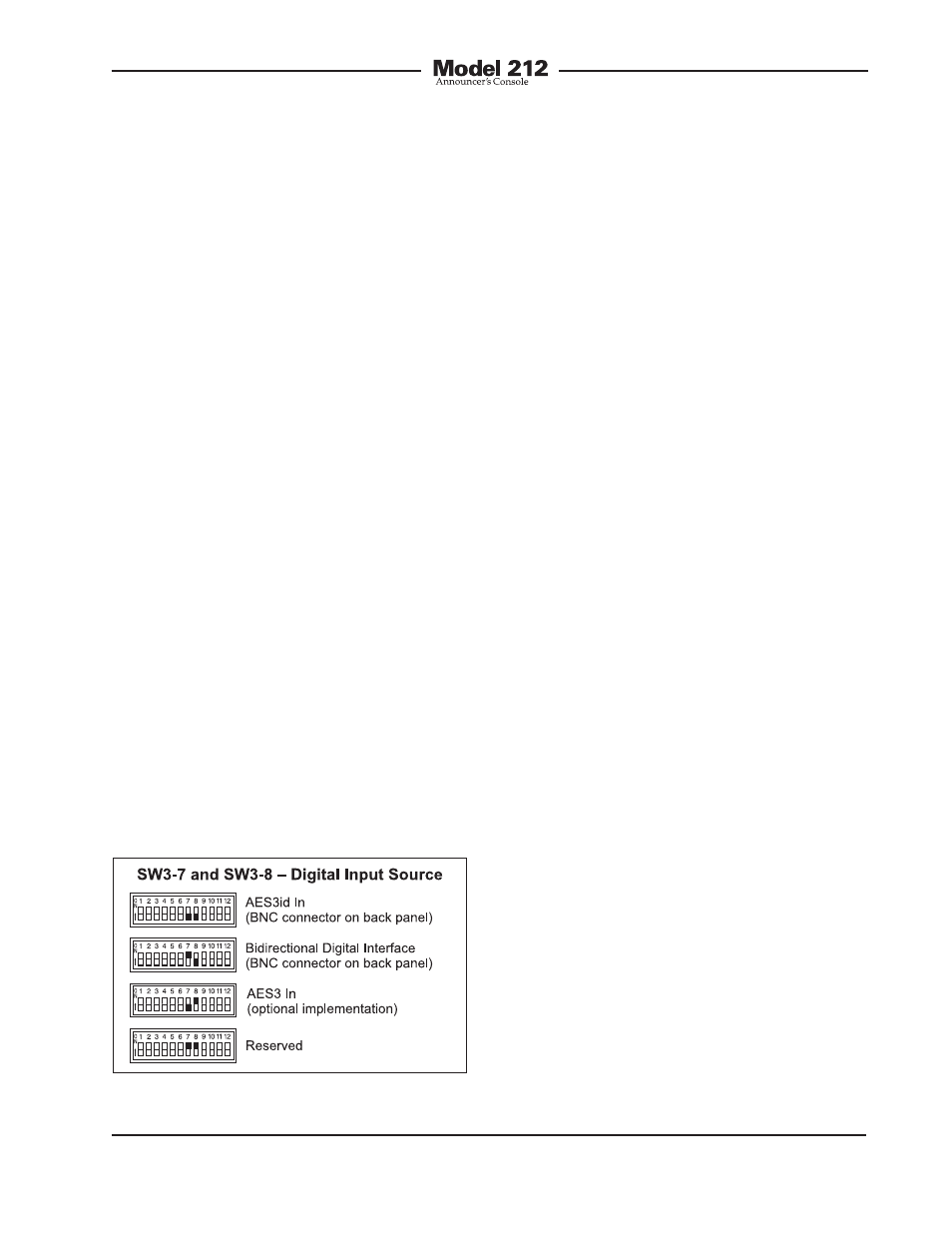
Digital Input Source
Switches SW3-7 and SW3-8 are used to
select which one of the three digital inter-
faces will be used by the Model 212 as its
audio source and reference clock input.
The two audio channels associated with
the selected digital input can be assigned
to the headphone output channels. In
addition, the clock signal derived from the
selected digital input is used by the digi-
tal audio circuitry. This clock signal is the
master “sync” reference that the Model
212 uses for the analog-to-digital conver-
sion and digital audio transmission func-
tions. The digital input interface choices
are AES3id In, bidirectional digital inter-
face, and AES3 In. As selecting the correct
interface is critical to proper Model 212
operation it’s worth describing each
in detail.
The AES3id input is located on the Model
212’s back panel and is compatible with
unbalanced 75 ohm digital audio signals.
This type of signal is common to broad-
cast facilities where audio and video utilize
a common cabling-type and BNC connec-
tors for signal transport. Note that many
Figure 13. Digital input source settings