Configuration, Microphone preamplifier gain and phantom power – Studio Technologies M212-00151 User Manual
Page 14
Issue 2, June 2006
Model 212 User Guide
Page 15
Studio Technologies, Inc.
Configuration
For the Model 212 to support the needs
of specific applications a number of op-
erating parameters must be configured.
These include microphone preamplifier
gain, phantom power on/off, headphone
cue source selection, headphone mono/
stereo mode, and a number of operating
modes. Two 8-position and one 12-posi-
tion DIP-type switch assemblies are used
to establish the desired configuration.
These switch assemblies are referred to
as Switch 1, Switch 2, and Switch 3, with
individual switches designated as SW1-1,
SW1-2, etc. The switch assemblies are
accessed through openings in the bottom
of the Model 212’s enclosure. The enclo-
sure does not have to be disassembled to
gain access to the switches.
To prevent unauthorized personnel from
changing the configuration settings, a se-
curity plate is attached to the bottom of the
Model 212’s enclosure. For convenience,
a configuration settings label is attached
to the security plate. It provides a summary
of the configurable parameters and related
information. Refer to Appendix A for a
representative view of the label. The secu-
rity plate is held in place by means of four
rubber bumpers (“feet”) that have built-in
screws. Using your fingers, remove the four
bumpers so that the plate can be removed.
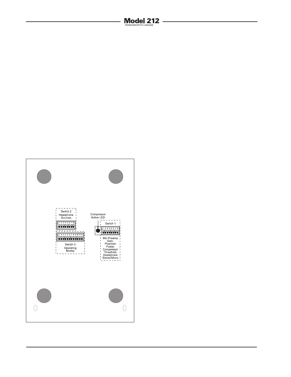
Refer to Figure 3 for a detailed view of the
configuration switch assemblies.
Microphone Preamplifier Gain
and Phantom Power
Five switches are used to set the gain of
the microphone preamplifier. One switch
is used to select the on/off status of the
phantom power supply.
Microphone Preamplifier Gain
Switches SW1-1 through SW1-5 are used
to select the gain of the microphone pre-
amplifier. The choices are 10, 20, 30, 40,
and 50 dB. Only one switch should be
enabled at a time. There’s no problem
changing the gain setting while the unit
is operating. Audio clicks or pops might
occur during gain transitions, but this
shouldn’t be a major issue as long as
associated monitor loudspeakers are
temporarily attenuated or muted.
Selecting the correct amount of gain for
an application might take a little experimen-
tation. The goal is to bring the mic’s signal
Figure 3. Bottom view of Model 212 showing
configuration switches and compressor active
LED