Operation, Conclusion, Pushbutton switches and status leds – Studio Technologies 212 2013 User Manual
Page 24
Issue 5, May 2013
Model 212 User Guide
Page 24
Studio Technologies, Inc.
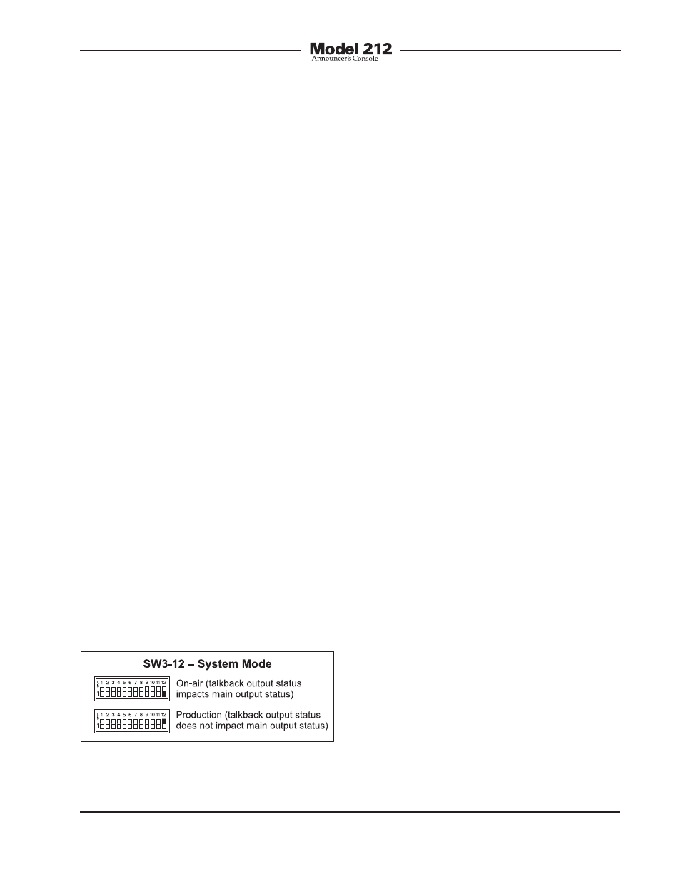
System Modes
Switch SW3-12 is used to configure the
overall operating mode of the Model 212.
Specifically, it determines how the main
output channel operates vis-à-vis the
talkback output channel. Understanding
how the two modes impact overall system
operation will ensure that correct opera-
tion and maximum usability will occur.
When the On-Air mode is selected, the
main output channel will mute (minimum
digital audio signal level or –infinity) when-
ever the talkback output channel is ac-
tive. The on-air mode should be selected
for all on-air broadcast applications. It’s
imperative that the main output channel
be muted whenever on-air talent uses the
talkback output channel to communicate
with production personnel.
When the system mode is set for Produc-
tion, the main output channel is never
muted in response to the talkback output
channel being active. In this way the main
and talkback output channels can be used
independently, with neither impacting the
other. An example of where this would be
useful is allowing the Model 212 to provide
two independent talkback functions; the
main and talkback buttons can be used
independently or simultaneously. The
Production mode can prove very useful
when selected for the correct application,
but it’s not appropriate for on-air use!
Conclusion
Once the multitude of DIP switches have
been set to their desired configuration,
the security plate should be reattached.
The four rubber bumpers should be hand-
tightened only. No tools should be used.
Operation
At this point the desired input, output,
and power connections should have been
made. The button labels may have been
revised. Finally, the configuration switches
should have been set. Normal operation of
the Model 212 can now begin. The unit will
begin functioning as soon as the source of
nominal 24 volts DC is connected.
Upon Model 212 power up, the three
status LEDs will light in succession as a
firmware “boot up” indication. The unit will
then begin normal operation. Depending
on the selected configuration, one LED
associated with the status of the main out-
put may be lit. The user is now presented
with two buttons, three LEDs, and two
rotary controls. These are simple to oper-
ate and understand, as will be described
in the following paragraphs.
Pushbutton Switches and
Status LEDs
Two pushbutton switches are used to con-
trol the main and talkback output chan-
nels. The way each operates depends
on the selected configuration. Three LED
indicators are located adjacent to the but-
tons. They reflect the status of the main
and talkback output functions.
Figure 16. System mode settings