Studio Technologies 212 2013 User Manual
Page 22
Issue 5, May 2013
Model 212 User Guide
Page 22
Studio Technologies, Inc.
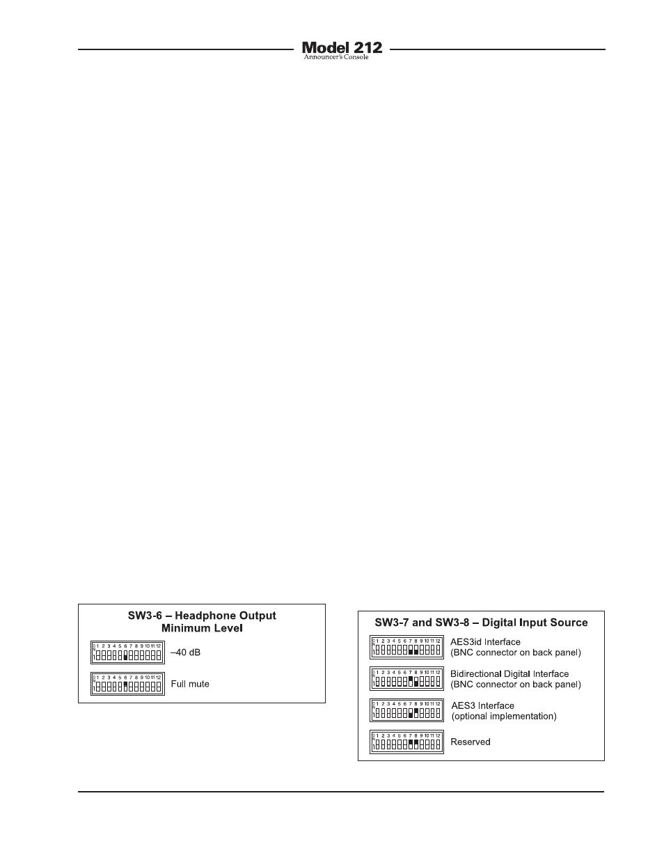
Digital Input Source
Switches SW3-7 and SW3-8 are used to
select which one of the three digital inter-
faces will be used by the Model 212 as its
audio source and reference clock input.
The two audio channels associated with
the selected digital input can be assigned
to the headphone output channels. In ad-
dition, the clock signal derived from the
selected digital input is used by the digital
audio circuitry. This clock signal is the
master “sync” reference that the Model
212 uses for the analog-to-digital conver-
sion and digital audio transmission func-
tions. The digital input interface choices
are AES3id In, bidirectional digital inter-
face, and AES3 In. As selecting the correct
interface is critical to proper Model 212
operation it’s worth describing each
in detail.
The AES3id input is located on the Model
212’s back panel and is compatible with
unbalanced 75 ohm digital audio signals.
This type of signal is common to broad-
cast facilities where audio and video
utilize a common cabling-type and BNC
connectors for signal transport. Note that
many people refer to this generically as
an “AES” digital audio signal. This can
be confusing but is not inaccurate. Previ-
ously there were separate standards for
Minimum Level Mode
Switch SW3-6 is used to configure the
headphone output’s minimum level. In the
–40 dB mode the minimum headphone
output level is 40 dB below maximum. The
headphone output channels will never fully
mute. This ensures that any audio signal
present on the selected cue audio source
will always be present on the headphone
output. In most on-air broadcast applica-
tions this is the appropriate setting.
When the full mute mode is selected, and
the level/level mode is also selected, mov-
ing either control to its fully counterclock-
wise position will cause its associated
channel to fully mute.
When the full mute mode is selected, and
the level/balance mode is also selected,
turning the level control to its fully coun-
terclockwise position will cause both
headphone channels to mute. Turning the
balance control to either its fully clock-
wise or fully counterclockwise position will
cause the appropriate channel to mute.
Selecting the full mute mode may be
appropriate for applications where mini-
mizing the chance of audio “leakage”
is important. This could occur when the
connected headset or headphones are
at times placed on a desk or tabletop.
Figure 14. Digital input source settings
Figure 13. Headphone output minimum level
settings