Studio Technologies 212 2013 User Manual
Page 23
Model 212 User Guide
Issue 5, May 2013
Studio Technologies, Inc.
Page 23
Incorrectly setting the digital input source
will probably prove to be the most com-
mon cause of incorrect Model 212 opera-
tion. Carefully reviewing the connected
signals and then selecting the appropriate
interface will lead to successful operation.
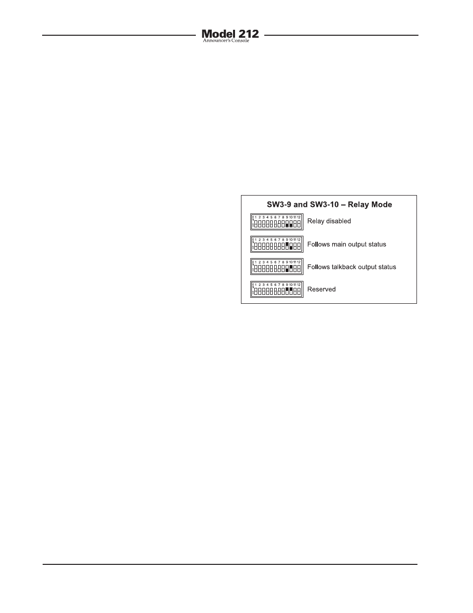
Relay Mode
Switches SW3-9 and SW3-10 are used
to configure the operating mode of the
auxiliary relay.
Figure 15. Relay mode settings
75 ohm unbalanced (AES3id) and 110
ohm balanced (AES3) digital audio sig-
nals. However, that was revised under
a newer revision of the AES3 standard
which now covers both balanced and
unbalanced implementations.
The bidirectional digital interface is a
special type of 75 ohm unbalanced signal
that carries two channels of digital audio
in each direction. To clarify, over a single
unbalanced cable two channels of digital
audio are sent in one direction and two
channels of digital audio are sent in the
other. The bidirectional digital interface
uses a BNC connector which is located
on the Model 212’s back panel. The inter-
face is only appropriate for use in carefully
engineered systems that are compatible
with this type of signal. An example ap-
plication is where a Model 212 is directly
interfaced with a 75 ohm port on a Riedel
digital matrix intercom system.
AES3 input circuitry is located inside the
Model 212’s enclosure and is compatible
with balanced 110 ohm digital audio sig-
nals. This type of signal is typically found
in non-broadcast applications where the
use of twisted pair wiring with a maximum
interconnection length of 100 meters does
not pose a problem. The Model 212 pro-
vides the AES3 input circuitry for installer-
selected applications where the desired
connector is mounted into one of the
spare connector locations on the Model
212’s back panel. Many applications use
standard 3-pin female XLR connectors for
AES3 inputs. However, using other con-
nector types, such as Neutrik EtherCon,
can be a convenient way of transporting
a number of different signals over “CAT5”
or “CAT6” twisted-pair cable.
Three modes are available:
• Relay is disabled: In this mode the relay
is disabled and will never change state.
• Follows main output status: In this mode
the relay will follow the state of the main
output channel. Specifically, the relay
will change state (energize) whenever
the main output channel is active.
• Follows talkback button status: In this
mode the relay will follow the state of the
talkback output channel. Specifically,
the relay will change state (energize)
whenever the talkback output channel
is active.