Operation, Conclusion, Pushbutton switches and status leds – Studio Technologies 210 2012 User Manual
Page 22
Issue 5, September 2012
Model 210 User Guide
Page 22
Studio Technologies, Inc.
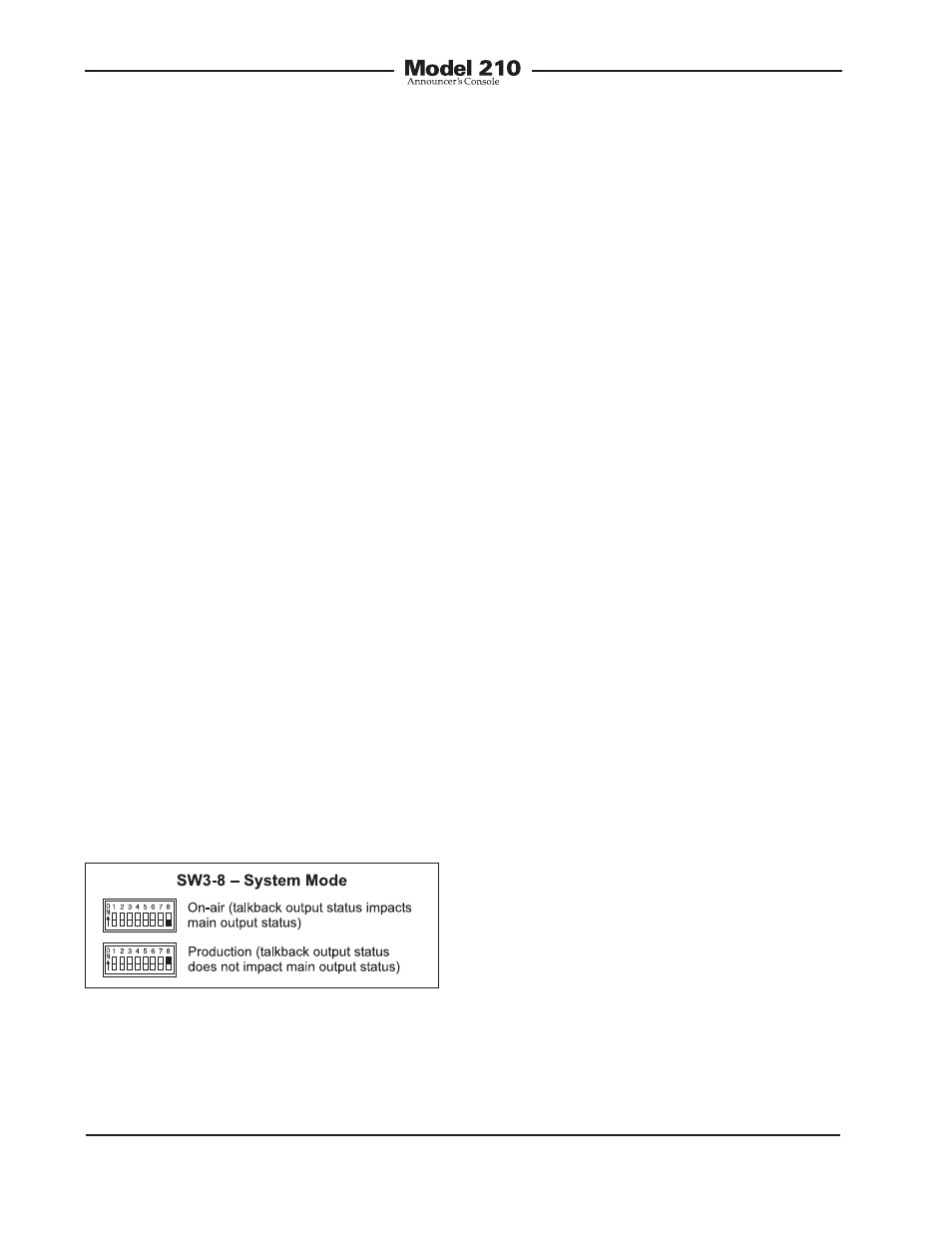
System Mode
Switch SW3-8 is used to configure the
overall operating mode of the Model 210.
Specifically, it determines how the main
output operates vis-à-vis the talkback out-
put. Understanding how the two modes
impact overall system operation will en-
sure that correct operation and maximum
usability will occur. When selected to the
on-air mode, the main output will mute
whenever the talkback output is active.
The LED indicators associated with the
main output will light accordingly. The on-
air mode should be selected for all on-air
broadcast applications. It’s imperative that
the main output be muted whenever on-air
talent uses the talkback output to commu-
nicate with production personnel.
When the system mode is set for produc-
tion, the main output is never muted in
response to the talkback output being
active. This mode allows the main output
to be used, for example, as an additional
talkback output. In this way the main and
talkback outputs can be used indepen-
dently, with neither impacting the other.
This also allows both buttons to be used
simultaneously. When selected for the cor-
rect application, the production mode can
prove to be very useful. But it’s not appro-
priate for on-air use!
Conclusion
Once the switches have been set to the
desired configuration, the security plate
should be reattached. The four rubber
bumpers should be hand-tightened only.
No tools should be used.
Operation
At this point the desired input, output,
and power connections should have been
made. The button labels may have been
revised. Finally, the configuration switches
should have been set. Normal operation
of the Model 210 can now begin. The
unit will begin functioning as soon as a
power source is connected. As previ-
ously discussed, the power source can be
provided by an IFB circuit, an external 24
volt DC power source, or both. It’s impor-
tant to highlight the fact that the Model
210 is an active device. Audio signals will
not be present on the outputs if correct
power has not been supplied. Specifically,
the microphone does not passively “cut
through” to the main output connector!
Upon Model 210 power up, the three
status LEDs will light in succession as a
firmware “boot up” indication. The unit will
then begin normal operation. Depending
on the selected configuration, one LED
associated with the status of the main out-
put may be lit. The user is now presented
with two buttons, three LEDs, and two
rotary controls. These are simple to oper-
ate and understand, as will be described
in the following paragraphs.
Pushbutton Switches and
Status LEDs
Two pushbutton switches are used to
control the main and talkback outputs.
Figure 15. System mode settings