Headphone output mode – Studio Technologies 210 2012 User Manual
Page 18
Issue 5, September 2012
Model 210 User Guide
Page 18
Studio Technologies, Inc.
their on positions. Note that using another
Model 210 at the “spotter” location could
also prove effective. It would provide all
the necessary microphone preamplifier,
talkback routing, and headphone monitor-
ing resources.
Note that in some cases a user may
wish to wear a headset or a pair of head-
phones in a left/right orientation opposite
of what’s usual. In this situation the trans-
ducer designated for the left ear would
actually supply audio to the user’s right
ear, and vice versa. A specific application
when this occurs is where on-air talent
needs to have a headset’s boom micro-
phone come across the right side of their
face, rather than the more-typical left side.
In this case it’s important to select the
left- and right-channel headphone source
assignment accordingly. With the Model
210’s flexible source selection there’s no
reason why users, such as on-air talent,
shouldn’t have their cue sources assigned
correctly.
There may be cases where a monaural
“single-muff” headset or headphone will
be connected to the Model 210’s head-
phone output. In this case the desired
source(s) should be routed only to the left
channel. No sources should be assigned
to the right channel. This will eliminate the
short-circuit current that could occur when
a 2-conductor (monaural) plug is mated
with the Model 210’s 3-conductor (stereo)
headphone output jack.
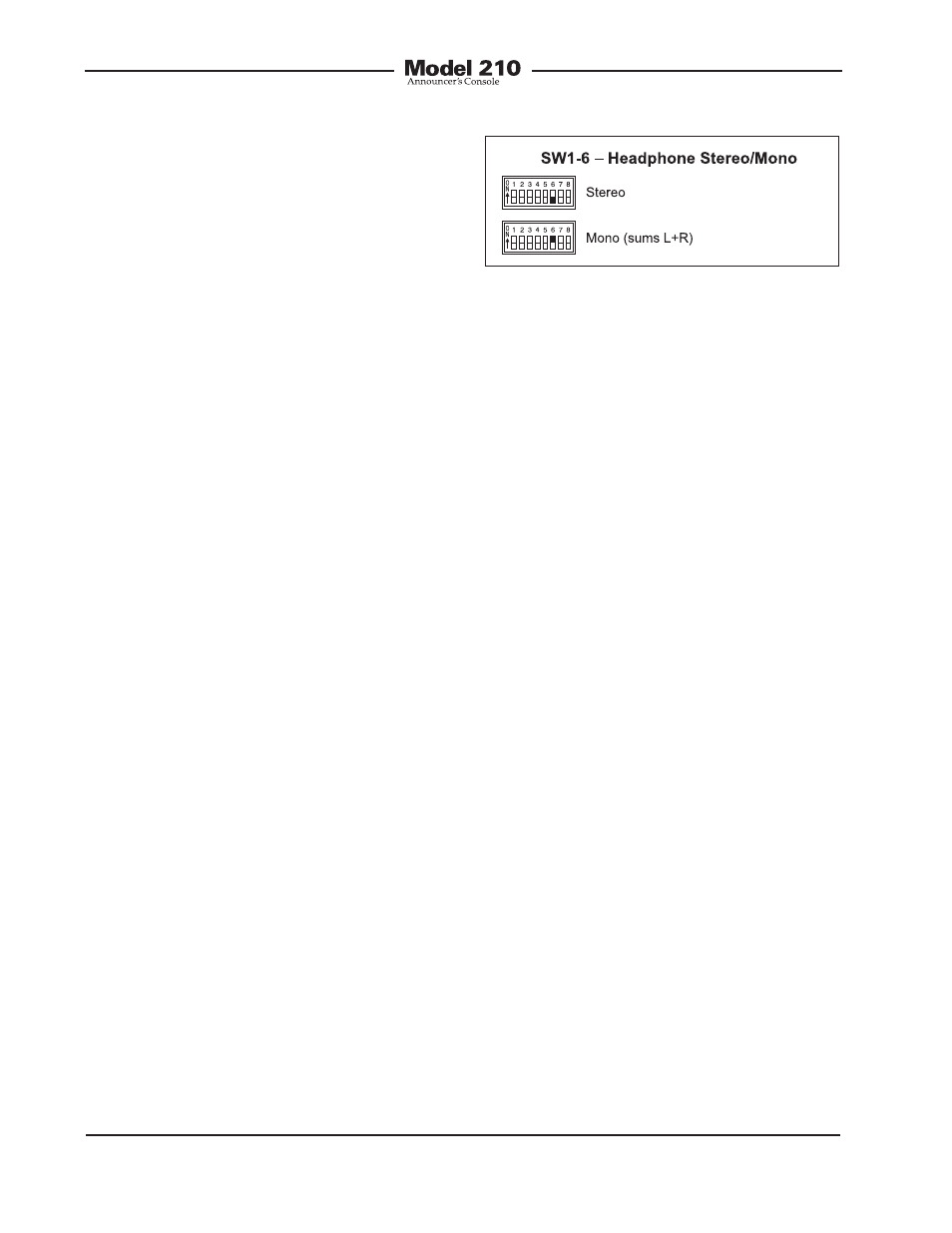
Headphone Output Mode
Switch SW1-6 allows a monaural head-
phone output to be created. This is
accomplished by summing (adding) the
selected left- and right-channel cue sig-
nals. The combined signals are sent to
both the left- and right-channel headphone
output driver circuits. The outputs of these
circuits connect, by way of 51 ohm series
protection resistors, to the headphone
output jack.
The headphone output monaural mode
feature was specifically included so that
a special 2-channel headphone mix mode
can be created. By enabling the mono
mode, the two front-panel user level con-
trols (“pots”) can be used to create the
desired “mix” of signals being sent to the
headphone output. Many applications,
especially in production settings, can
benefit from this capability. The desired
cue sources must be carefully assigned
to take advantage of the monaural mode.
The first cue source should be assigned,
using the DIP-type switches, to the left
channel. Its output level will be adjusted
by the left control. The second cue source
should be assigned to the right channel.
Its output level will be adjusted by the right
control.
There is one limitation related to the head-
phone mono output mode. It’s the fact
that the output will be 2-channel mon-
aural. Whatever signal is present on the
headphone output’s left channel will also
be present on the right channel. A stereo
headphone mix can’t be created. But in
most cases this limitation won’t over-
shadow the benefit of being able to create
the mix. For signal-flow clarification please
review the block diagram located at the
end of this user guide.
Figure 8. Headphone output mode settings