Headphone source selection – Studio Technologies 210 2012 User Manual
Page 17
Model 210 User Guide
Issue 5, September 2012
Studio Technologies, Inc.
Page 17
Phantom Power On/Off
The Model 210 can provide 48 volt nomi-
nal phantom power to the microphone
input. Switch SW1-8 controls whether or
not phantom power is active. By phantom
power’s very nature it could be left applied
to the microphone input at all times. But
generally people prefer to turn it off unless
required for a specific microphone.
the left and right headphone channels.
This would entail setting switches SW2-2
and SW2-6 to their on positions. All
other switches would remain in their
off positions.
A more complex application might have
a 2-channel IFB circuit connected to the
Model 210, with an optional line input
card installed and line-level audio from
a golf event “spotter” connected to that.
In a case such as this, it would be typi-
cal for IFB channel 1 to be assigned to
the head-phone’s left channel, IFB chan-
nel 2 assigned to the right channel, and
auxiliary input 1 also assigned to the right
channel. This would allow both IFB chan-
nel 2 and “spotter” audio to be heard in
the head-phone’s right-channel output. To
achieve this would require that switches
SW2-1, SW2-6, and SW2-7 be placed in
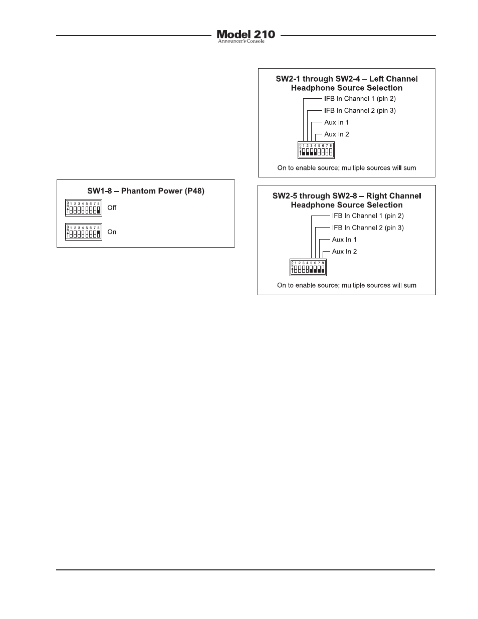
Figure 7. Left and right channel headphone
source selection settings
Figure 6. Phantom power switch settings
Headphone Source Selection
Switch assembly SW2 is used to configure
the source or sources that are routed to
the stereo headphone output. The head-
phone sources are IFB channel 1, IFB
channel 2, auxiliary input 1, and auxiliary
input 2. The IFB channels are provided by
way of the IFB input connector located on
the Model 210’s back panel. The auxiliary
inputs are available only if the optional
line input cards have been installed or a
special Model 210 configuration has been
implemented.
Each of the available input sources can
be assigned to the headphone output’s
left channel, right channel, or both the
left and right channels. The Model 210’s
circuitry allows any combination of input
assignments to be made. For example,
consider the situation where a single-
channel IFB system, with both program
and interrupt audio on pin 3, is connected
to the Model 210. In this case it may be
desirable to assign this IFB signal to both