Restore factory defaults, Model 71 control console configuration – Studio Technologies 780-03 V.4.15 User Manual
Page 23
Model 780-03/790 User Guide
Issue 1, April 2015
Studio Technologies, Inc.
Page 23
for Surround
cases one channel should serve as the
overall reference level and not be changed.
This is typically the center channel.
This feature is provided primarily for use
when the post-fader monitor output chan-
nels are connected to loudspeaker sys-
tems that don’t offer a means of “trimming”
the input sensitivity of individual channels.
Without this capability, minor adjustments
to the output level of specific loudspeakers
to account for room acoustics wouldn’t be
possible.
It’s also possible to use the StudioComm’s
output level offset capability to adjust the
overall post-fader monitor output levels to
allow matching to the input sensitivity of
loudspeaker systems. In this case all of
the output channels would be configured
to have the same output level offset set-
ting. For example, the eight channels could
all be configured to have a –3.5 dB output
level offset. However, great care must be
taken when configuring a system in this
manner. The dynamic range or noise floor
of the audio signals will be impacted and
settings of greater than a few dB could
lead to poor monitor system performance.
Restore Factory Defaults
The restore factory defaults function is
provided primarily for factory use. In this
way a system can be quickly set so that
its default settings are selected. While you
are welcome to use this function, be care-
ful so that your configuration efforts aren’t
wasted. Specifically, be aware that the ref-
erence level is reset to minimum level. All
the other parameters are fairly easy to set
up, but resetting the reference level would
require getting out an SPL meter and a
calibrated signal source. This is a hassle
you may not need!
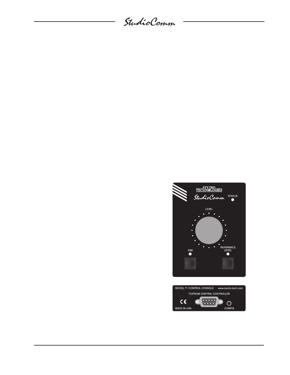
Model 71 Control Console
Configuration
Two configuration choices are available on
each Model 71. One is its device address
and the other is the button disable mode. A
configure button is located on the back of
each Model 71 Control Console, adjacent
to the 9-pin female D-subminiature con-
nector. Pressing and holding this button
for two seconds places this specific unit in
its configuration mode; normal operation
of the Model 780-03 and other connected
Model 71 and Model 790 units will con-
tinue. When a Model 71 enters its configu-
ration mode its three LEDs will no longer
perform their usual functions. Instead the
status LED will blink to indicate that con-
figuration mode is active. Refer to Figure 9
for details.
Figure 9. Model 71 Control Console Front and
Back Panels