Studio Technologies 41 2004 User Manual
Page 8
Model 41 User Guide
Issue 1, October 2004
Studio Technologies, Inc.
Page 9
connected. In this situation the left source
would be connected to input channel one
while the right source would be connected
to input channel two. This might also
be the case with other professional audio
applications, such as recording and post-
production.
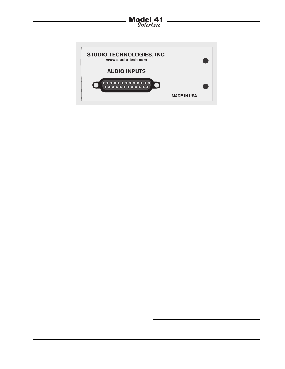
Audio input connections are made by way
of one female 25-pin D-subminiature con-
nector which is located on the Model 41’s
back panel. A cable harness is required
with a 25-pin D-sub plug (male) on one
end and the desired mating connectors
on the other. This cable harness is not sup-
plied by Studio Technologies. (Note that in
some locations the term “cable loom” may
be used instead of “cable harness.”) The
wiring scheme used by the D-sub complies
with the now-ubiquitous one made familiar
by TASCAM® with their DA-88® product.
A wiring harness prepared for connection
to the Model 41’s audio inputs is identical
to a DA-88-style input harness. Please refer
to Figures 2 and 3 for connection details.
Note that unlike a DA-88-style harness,
the Model 41’s D-sub connector’s hold-
down screws use 4-40 threads. This com-
plies with the original design standard for
D-subminiature connectors which used
English rather than metric thread pitch.
Signal
Signal
Connections
High (+)
Low (–)
Shield
IFB Circuit 1-Interrupt
24
12
25
IFB Circuit 1-Program
10
23
11
IFB Circuit 2-Interrupt
21
9
22
IFB Circuit 2-Program
7
20
8
IFB Circuit 3-Interrupt
18
6
19
IFB Circuit 3-Program
4
17
5
IFB Circuit 4-Interrupt
15
3
16
IFB Circuit 4-Program
1
14
2
Notes: 1) Connector type on Model 41 is 25-pin
D-subminiature female. Installer must provide plug
(male). Connector uses 4-40 threaded inserts for
locking with mating plug.
2) Wiring scheme follows TASCAM DA-88 convention.
Standard DA-88-style wiring harnesses are directly
compatible, with the exception of 4-40 screw threads
being
required.
Figure 2. Connections for Audio Inputs using
IFB Nomenclature
Figure 1. Detail of back panel showing connector used for audio inputs
The Model 41’s audio input circuits have
a nominal signal level of +4 dBu. They
are transformer coupled, have a nominal
impedance of 10 k ohms, and compatible
with balanced or unbalanced sources.
Balanced sources should be wired so that
signal high is connected to the + pins,
signal low to the – pins, and shield to the
shield pins. With unbalanced sources,
connect signal high to the + pins, and
shield to both the – and the shield pins.