Troubleshooting, Operating parameters, If the model 41 doesn’t work at all – Studio Technologies 41 2004 User Manual
Page 14
Model 41 User Guide
Issue 1, October 2004
Studio Technologies, Inc.
Page 15
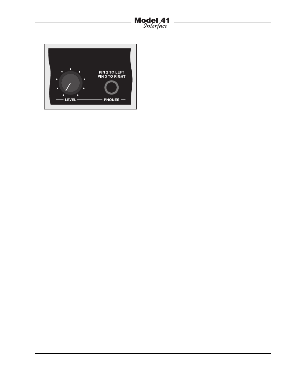
channels. Should it be necessary, there’s
no reason why the headphone output
couldn’t also be used as a line-level
monitor output.
Operating Parameters
As expected with professional equipment,
whenever mains power is disconnected
from the Model 41, the existing state of the
monitor section is stored in non-volatile
memory. This ensures that upon subse-
quent “power up” the unit will return to
how it was left. For example, if the auto
scan function was active when the Model
41 was powered down, auto scan will be-
gin once mains power is again connected.
Troubleshooting
If you’re having trouble getting the Model
41 up and running, this section may help.
If you haven’t read the previous sections
of this guide, you should do so before
proceeding.
If the Model 41 Doesn’t Work
At All
A source of AC mains power must be
connected to the Model 41. The unit is
a “universal input” type so that applying
anything between 100 and 230 volts, 50/60
Hz is acceptable. Whenever mains power
is connected the four monitor status LEDs
should go through their power-up routine,
lighting one at a time in sequence. If this
does not occur confirm that AC mains
power is active (“hot”) and that the cord is
securely mated with the inlet connector on
the Model 41’s back panel.
In all foreseeable situations, both normal
and abnormal, the status LEDs should
go through the normal power-up routine.
However, it’s possible that if all four IFB
circuits are being presented with a short-
circuit condition, the internal 36 volt power
supply may enter its protection mode and
shut down. In this case no LED will light. If
the LEDs present this scenario, even after
confirming that mains power is correctly
being applied, try removing the loads from
the IFB circuits. The easiest way to do this
is to remove the 3-pin female XLR-type
connectors that are plugged into the Model
41’s back panel. If normal operation then
begins, carefully check the IFB circuit wir-
ing for fault conditions.
If the status LEDs still don’t go through
their power-up routine, even after con-
firming that mains power is present and
that the IFB circuits are not shorted, it’s
likely that the unit requires factory service.
For safety in the event of a major internal
failure, the internal 36 volt power supply
contains a fuse in series with the incoming
mains power. This fuse will open (“blow”)
only if a serious failure occurs inside the
unit. The fuse is not field-replaceable.
The Model 41 must be returned to the
factory, or an authorized service location,
for review and repair.
Figure 8. Detail of front panel showing
headphone section