Operation, Audio integrity – Studio Technologies 41 2004 User Manual
Page 12
Model 41 User Guide
Issue 1, October 2004
Studio Technologies, Inc.
Page 13
Audio Integrity
At this stage the Model 41 should have
been installed and the input levels ad-
justed as required. The unit should now
be ready for many years of excellent per-
formance. But before turning to another
task, performing a final Model 41 “reality
check” is highly recommended. Using
the monitor section, along with a pair of
high-quality stereo headphones, carefully
listen to each channel associated with the
four IFB circuits. Ensure that the correct
audio sources are assigned to the cor-
rect IFB circuits. Confirm that all interrupt
channels have the correct audio levels as
they switch from normal audio to interrupt
content. Overall, the audio quality should
be excellent, with no hum, noise, hiss, or
other objectionable content. Should any
issues be detected, now is the time to
work them out. Presenting IFB circuit us-
ers with a correctly implemented system
will make life better for everyone involved!
Operation
Overall, the Model 41 is designed for con-
tinuous operation with no adjustment or
maintenance required. On the input side,
maintaining the correct level coming from
the audio sources is very important. The
cabling that connects the Model 41’s IFB
circuits to the user devices must remain
free of full or partial short circuits. And
finally, the total current draw of the con-
nected user devices must remain at 200
milliamperes or less. The monitor section
will help ensure that proper operation is
taking place. It will also prove invaluable
assistance should an issue arise.
Monitor Section
The Model 41’s monitor section allows
audible and visual monitoring of the audio
signals present on the four IFB circuits.
In addition, continuous monitoring of the
DC output voltages on the circuits is also
performed. The “heart” of the monitor sec-
tion is logic circuitry created by a micro-
controller integrated circuit and associated
firmware. This adds some “smarts” to an
otherwise pedestrian function. Using four
electromechanical relays, the monitor
section accesses the IFB circuits directly
on the Model 41’s output connectors.
This ensures that the impact of the actual
wiring and connected user devices is also
monitored, rather than just something
internal to the Model 41’s circuitry.
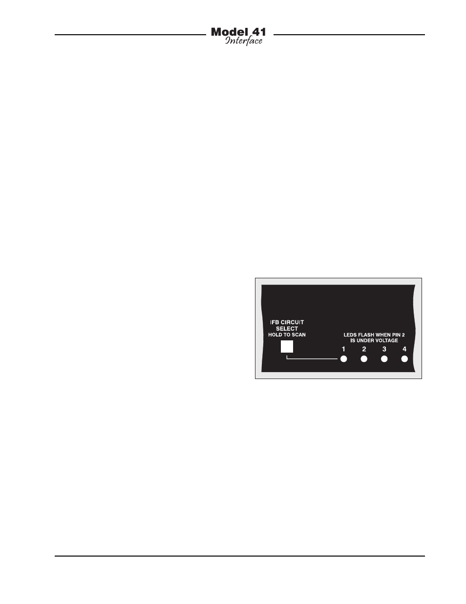
Figure 6. Detail of front panel showing four
status LEDs and associated pushbutton switch
Associated with the monitor section are
four status LEDs, one pushbutton switch,
two 5-segment LED level meters, a ro-
tary level control, and a headphone jack.
The four monitor status LEDs are used to
display two conditions: the circuit being
monitored and low DC output voltage.
One of the LEDs is always lit, indicating
which of the four IFB circuits is currently
being monitored by the meters and head-
phone output. In addition, each status
LED will flash on and off should the level