Studio Technologies 41 2004 User Manual
Page 13
Issue 1, October 2004
Model 41 User Guide
Page 14
Studio Technologies, Inc.
on pin 2 of its respective output connector
fall below 24 volts DC. This DC monitor-
ing function is very powerful, allowing a
proactive approach to be taken should an
interconnecting cable or IFB user device
issue arise.
The pushbutton switch serves two purpos-
es: selecting the source to be monitored
and enabling the auto scan feature. To
manually select an IFB circuit to be moni-
tored, press and release the button until
the status LED associated with the desired
IFB circuit lights. Each press of the but-
ton will advance the circuit number to be
monitored by one. A delay is built into the
circuit selection process allowing a user to
move from, for example, circuit 1 to circuit
3. Simply by pressing the button twice in
rapid succession circuit 2 will be automati-
cally skipped.
Unique to the Model 41 is its auto scan
feature. Pressing and holding the button
for two seconds will cause this feature to
begin operation. In this mode the monitor
source automatically “steps” through each
IFB circuit, pausing for eight seconds
before moving on to the next. Ideally, this
will allow technical personnel to observe
a problem through casual viewing of the
Model 41’s front panel.
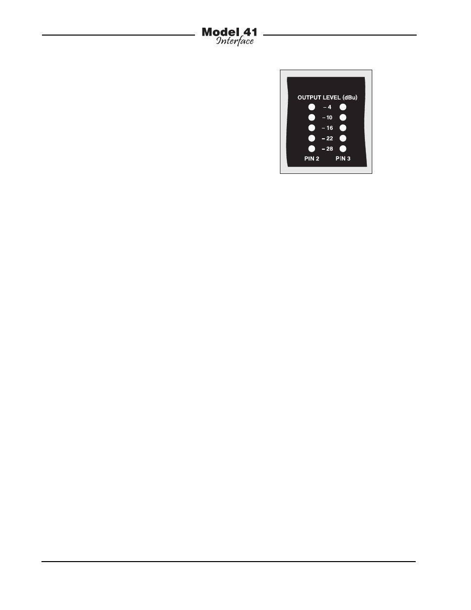
The dual 5-segment LED level meters al-
low a direct observation of the audio levels
present on pins 2 and 3 of the selected
IFB circuit’s output connector. In television
broadcast settings, the left meter will typi-
cally display the “interrupt” signal while
the right meter will display “program.” A
quick glance at the meters will give an
accurate overall indication of a circuit’s
performance. Upon initial power up, the
meters may be observed “bouncing” each
time the IFB circuit selected for monitoring
changes. This is normal, caused by DC
blocking capacitors taking a minute or
two to reach their final state.
It’s important to note that the meters on
the Model 41 are calibrated differently
from the typical “VU” scale. The level
steps were selected so as to effectively
display the IFB circuit’s nominal –10 dBu
signal level. The ballistics of the meters
is also different, being a cross between
VU and peak. The bottom four LEDs are
green in color and indicate that signals are
in the normal range. The top LED, yellow
in color, lights when signals are 6 dB or
greater above –10 dBu. A correctly func-
tioning IFB circuit should find signals light-
ing the four green LEDs, with the yellow
LED lighting only on peaks.
The headphone output allows audible
monitoring of the selected IFB circuit.
The 2-channel output is compatible with
virtually any pair of stereo headphones.
As the output circuitry meets “pro audio”
specifications, it’s recommended that
high-quality headphones be used. Pin 2
of the IFB circuit is the signal source for
the left channel of the headphone output.
Pin 3 of the IFB circuit is the source for the
right channel. The rotary control adjusts
the output level of both the left and right
Figure 7. Detail of front panel showing dual
5-segment LED level meters