Technical notes, Definition of level, Models 32a and 33a minimum output level – Studio Technologies 2A 2013 User Manual
Page 30: Dim/mute function
Issue 1, October 2013
Model 2A User Guide
Page 30
Studio Technologies, Inc.
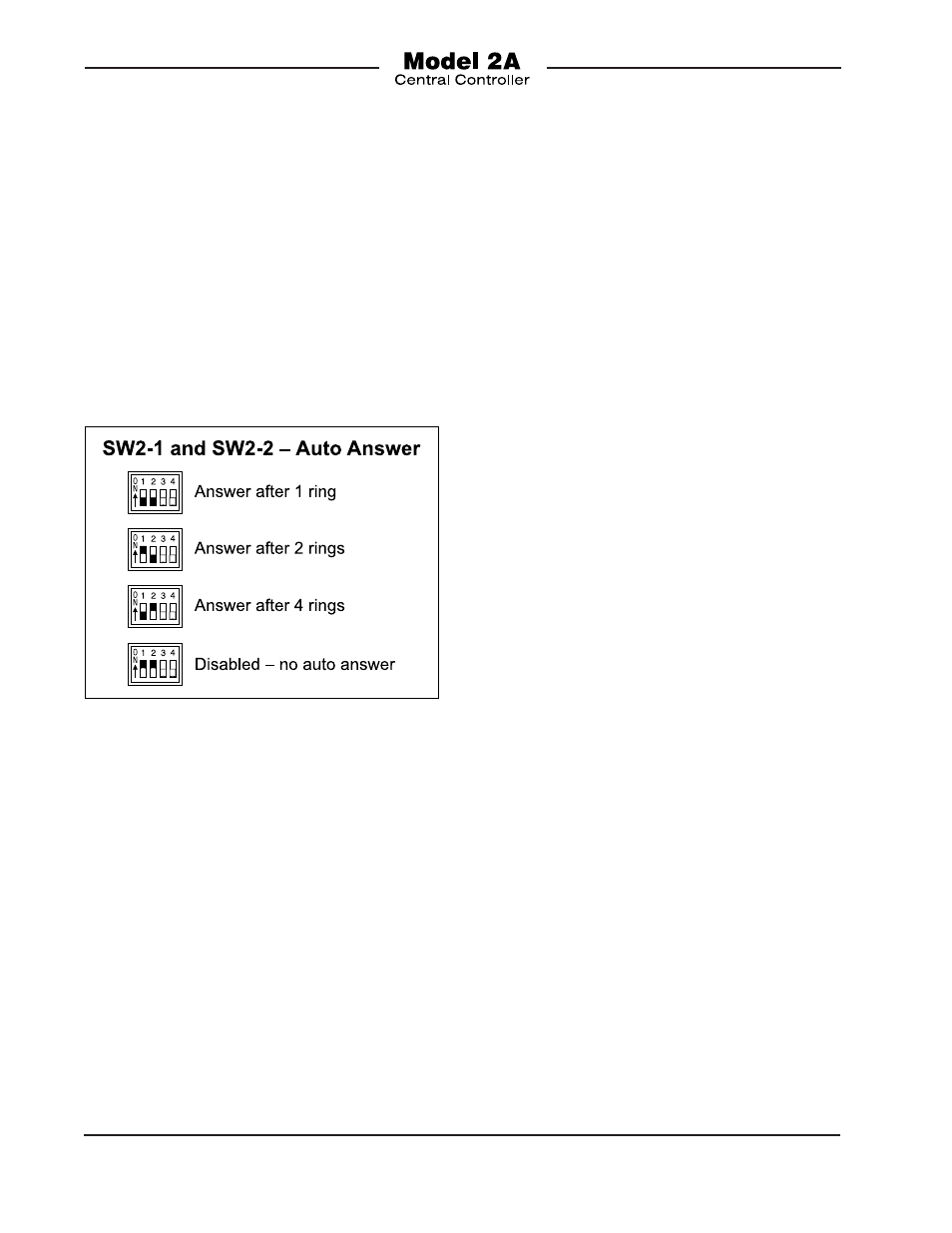
to be configured from among four choices:
answer after one, two, or four rings or dis-
able auto answer. The DIP switch, located
on the Model 2A’s printed circuit board, is
labeled SW2. It’s located between the 3-pin
female XLR connector for program input C
and the rotary level control for IFB chan-
nel 1. Access requires removing the unit’s
cover. You must observe proper safety pre-
cautions as highlighted in the Safety Warn-
ing section of this guide. Refer to Figure 10
for details on how to configure the switches.
Technical Notes
Definition of Level
Studio Technologies has opted to use the
dBu designation as it seems to be quite
rational. Using dBm was fine when all audio
line outputs were terminated with 600 ohm
loads. In this way it was easy to say that
0 dBm is 1 milliwatt dissipated in the known
load (i.e., 0 dBm across 600 ohms will mea-
sure 0.775 V). In current situations an output
is rarely terminated in 600 ohms; generally
5 k ohms or higher. The dBu designation is
better because it refers to dB referenced to
0.775 V, with no reference to load imped-
ance. This takes into account the current
audio scene where most equipment has a
low output source impedance and a high
input impedance.
Models 32A and 33A Minimum
Output Level
By design, the output level on the Model
32A and Model 33A Talent Amplifiers cannot
be set to fully “off.” While the output level can
be substantially attenuated, it never can be
set for full attenuation. This implementation
was selected to ensure that talent personnel
could never accidentally be fully “isolated”
from their program or IFB source. There may
be special cases where full attenuation is
desired. This might be especially true with
the Model 33A Talent Amplifier, where a mix
of the two IFB channels can be achieved.
Provisions on the Model 32A and Model
33A circuit boards have been made to allow
this to be modified. In the standard design a
fixed resistor in series with one side of the
level potentiometer prevents full attenuation.
By replacing this resistor with a “0 ohm”
resistor or jumper strap, full attenuation can
be achieved. Contact the factory for details.
Figure 10. Telephone Interface 2 Auto Answer
settings
Dim/Mute Function
From the factory, program audio is set to
fully mute upon interrupt. If level “dimming”
rather than full muting is desired, a modi-
fication can be performed by a qualified
technician. This would entail installing two
surface-mount fixed resistors in the Model
2A’s circuit board. This process requires
removing the Model 2A’s cover. You must
observe proper safety precautions as
highlighted in the Safety Warning section
of this guide. Contact the factory for details.