Studio Technologies 2A 2013 User Manual
Page 23
Model 2A User Guide
Issue 1, October 2013
Studio Technologies, Inc.
Page 23
IFB channels. Two momentary action
pushbutton switches are located on the
left end of the front panel and are labeled
IFB 1 and 2. Pressing either switch mutes
program audio, mutes the monitor speaker
output, and connects the front-panel
microphone to the selected IFB channel(s).
The red IFB status LED associated with
each channel will light whenever its corre-
sponding IFB button is pressed. Notice that
sound enters the microphone via the small
openings in the front panel above and
slightly to the right of the switches.
Program Select, Level Adjustment, and
Indicators
Two identical sets of controls and indica-
tors serve IFB channels 1 and 2. Each
channel contains six program select
switches, two status LEDs, a program level
control, and a 5-segment LED level meter.
The six switches are used to select which
of the four program inputs and two tele-
phone interface receive audio sources will
serve as the program audio source(s). The
switches were designed to allow more than
one source to be selected at a time. The
ability to simultaneously depress and lock
multiple buttons is not a defect but rather
a feature which can be useful in special
circumstances.
The red LED, labeled IFB, is lit any time
program audio is being interrupted. There
are three ways an interrupt can take place:
by the internal microphone being activated,
by a Model 22 or Model 24 Access Station
being used, or via a control signal from the
voice operated (VOX) interrupt function.
The yellow LED, labeled VOX, is lit any time
an interrupt condition is caused by the VOX
function.
The program level control allows the pro-
gram audio signal to be adjusted relative to
the interrupt audio level. The interrupt level
is internally fixed and serves as the refer-
ence. The gain structure was configured so
that the level control set for about 70 per-
cent of rotation (the “2-o’clock” position) will
give a program level approximately equal to
the interrupt level. This statement is made
under the assumption that a +4 dBu pro-
gram signal is selected and its associated
input trim pot is correctly set.
The 5-segment LED level meter displays
the internal level of the composite (pro-
gram and interrupt) IFB signal. The three
green LEDs are lit when the signal level is
in the normal operating range. The yellow
LED will light when signal level are slightly
higher than average. The red LED lights
when signal levels reach the “headroom”
area. The ballistics of the meter is a cross
between that of a VU meter and a peak
(PPM) meter. (We affectionately refer to it
as a “PU” meter!) The meter should prove
useful during installation and maintenance,
as well as during normal operation.
A typical interrupt signal will light the green
LEDs, with peaks lighting the yellow LED.
The internal compressor circuit will keep
most interrupt signals from lighting the red
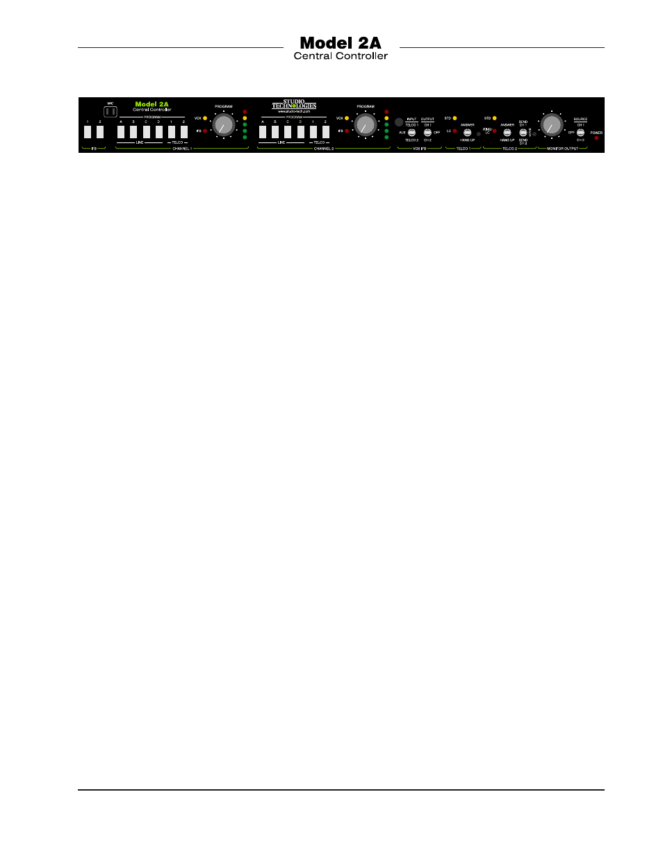
Figure 9. Detail of Model 2A Central Controller Front Panel