Technical notes, Safety warning, Configuring auto answer – Studio Technologies 2A 2015 User Manual
Page 31: Dim/mute function, Definition of level
Model 2A User Guide
Issue 2, March 2015
Studio Technologies, Inc.
Page 31
Peak signals should fall in the –5 to
0 dBu range. This trim pot setting should
result in a clean, clear interrupt signal,
without excess compressing by the
Model 2A’s circuitry.
Safety Warning
A competent technician is required to
perform any configuration changes that
entail accessing the Model 2A’s circuit
board. The cover of the Model 2A must
be removed, exposing the technician to
a potential shock hazard. Only after AC
mains power has been disconnected and
the mains cord removed from the back
of the Model 2A should the cover be re-
moved. Four screws, two on each side of
the chassis, are used to secure the cover.
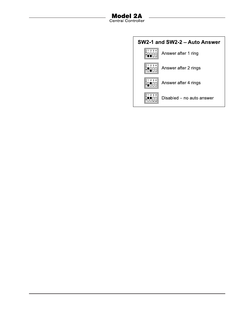
Configuring Auto Answer
From the factory the auto answer function
associated with telephone interface 2
(Telco 2) will typically be configured to
answer after detecting one cycle of ringing
voltage. This setting may be appropriate
for most applications. But some may ben-
efit from an alternate configuration. Two
switches, part of a 4-position DIP switch
assembly, allow the auto answer function
to be configured from among four choices:
answer after one, two, or four rings or dis-
able auto answer. The DIP switch, located
on the Model 2A’s printed circuit board,
is labeled SW2. It’s located between the
3-pin female XLR connector for program
input C and the rotary level control for
IFB channel 1. Access requires removing
the unit’s cover. You must observe proper
safety precautions as highlighted in the
Safety Warning section of this guide. Refer
to Figure 11 for details on how to configure
the switches.
Dim/Mute Function
From the factory, program audio is set to
fully mute upon interrupt. If level “dimming”
rather than full muting is desired, a modi-
fication can be performed by a qualified
technician. This would entail installing two
surface-mount fixed resistors in the Model
2A’s circuit board. This process requires
removing the Model 2A’s cover. You must
observe proper safety precautions as
highlighted in the Safety Warning section
of this guide. Contact the factory for details.
Technical Notes
Definition of Level
Studio Technologies has opted to use the
dBu designation as it seems to be quite ra-
tional. Using dBm was fine when all audio
line outputs were terminated with 600 ohm
loads. In this way it was easy to say that
0 dBm is 1 milliwatt dissipated in the
known load (i.e., 0 dBm across 600 ohms
will measure 0.775 V). In current situations
an output is rarely terminated in 600 ohms;
generally 5 k ohms or higher. The dBu des-
ignation is better because it refers to dB
Figure 11. Telephone Interface 2 Auto Answer
settings