Operation – Studio Technologies 2A 2015 User Manual
Page 24
Issue 2, March 2015
Model 2A User Guide
Page 24
Studio Technologies, Inc.
Operation
The Model 2A’s Front-Panel Controls
and Indicators
If you value equipment by the number of
switches and lights per rack space, the
Model 2A is really a standout—there is
more stuff crammed onto the front panel
than we thought possible! Seriously, the de-
signers had the difficult problem of getting
maximum functionality into a single rack
space. They had heated arguments about
the feature list, what to include, what to
delete. In the end, we feel that all important
features were included. Once you under-
stand all the functions, we think you’ll find
the Model 2A quite powerful, yet easy and
intuitive to use.
Looking at the Model 2A’s front panel from
the left to the right, you should note the
functional groups: internal interrupt mi-
crophone, channel 1-related items, chan-
nel 2-related items, voice activated (VOX)
interrupt, telephone interface 1, telephone
interface 2, monitor output, and power LED.
We’ll discuss these groups in the
following sections.
Internal Interrupt Microphone
The Model 2A contains an internal micro-
phone which can be used to access the
IFB channels. Two momentary action push-
button switches are located on the left end
of the front panel and are labeled IFB 1 and
2. Pressing either switch mutes program
audio, mutes the monitor speaker output,
and connects the front-panel microphone
to the selected IFB channel(s). The red IFB
status LED associated with each channel
will light whenever its corresponding IFB
button is pressed. Notice that sound enters
the microphone via the small openings in
the front panel above and slightly to the right
of the switches.
Program Select, Level Adjustment, and
Indicators
Two identical sets of controls and indicators
serve IFB channels 1 and 2. Each chan-
nel contains six program select switches,
two status LEDs, a program level control,
and a 5-segment LED level meter. The six
switches are used to select which of the four
program inputs and two telephone inter-
face receive audio sources will serve as the
program audio source(s). The switches were
designed to allow more than one source to
be selected at a time. The ability to simulta-
neously depress and lock multiple buttons is
not a defect but rather a feature which can
be useful in special circumstances.
The red LED, labeled IFB, is lit any time
program audio is being interrupted. There
are three ways an interrupt can take place:
by the internal microphone being activated,
by a Model 22 or Model 24 Access Station
being used, or via a control signal from the
voice operated (VOX) interrupt function. The
yellow LED, labeled VOX, is lit any time an
interrupt condition is caused by the VOX
function.
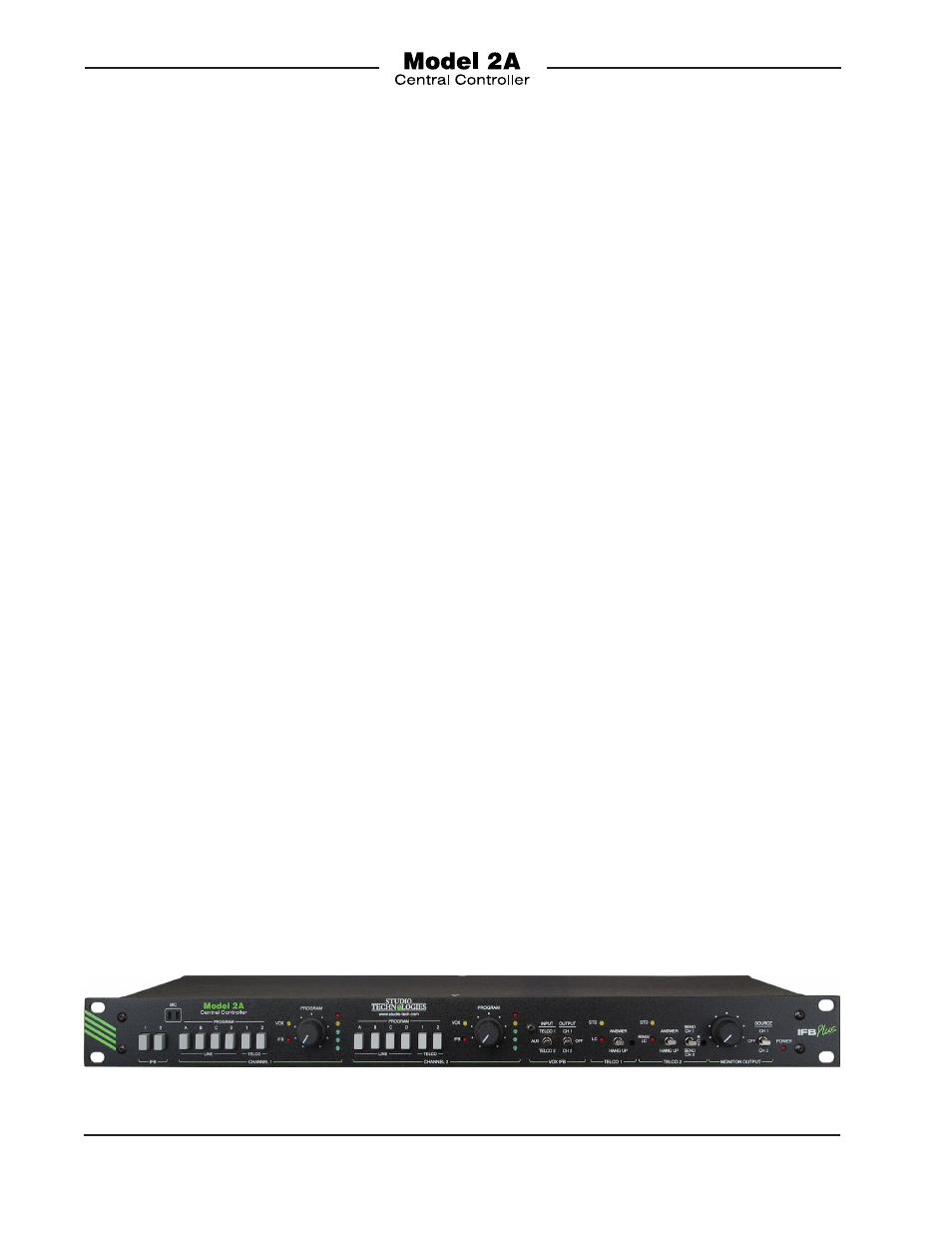
Figure 10. Detail of Model 2A Central Controller Front Panel