Model 24 access station – Studio Technologies 2A 2015 User Manual
Page 10
Issue 2, March 2015
Model 2A User Guide
Page 10
Studio Technologies, Inc.
The two high-quality backlit pushbutton
switches provide access to the Model 2A’s
two IFB channels. The lights in the switch-
es display when an interrupt is taking place
on its respective channel; lighting brightly
when IFB is active and dim when IFB is
idle. An input select switch allows connec-
tion of a Model 11A Gooseneck Micro-
phone or external line-level signal source.
The electronically balanced line-level input
allows interfacing with other communica-
tions equipment, such as “hot mic” signals
from an intercom user station.
The Model 22 can be configured to mute
the Model 2A’s monitor amplifier output.
This function will prevent acoustic feed-
back from occurring when a Model 22 is
located close to the Model 2A’s monitor
speaker.
Model 22 Access Stations are linked to the
associated Model 2A Central Controller via
9-pin D-subminiature female connectors.
Each access station contains two connec-
tors, allowing a simple daisy-chain installa-
tion. The nine leads carry all signals; audio,
control, status lamp (tally), and power. The
Model 2A provides all power required by
the access stations. The Model 25A 19-
Inch Rack Adapter is available to mount
a Model 22 and a Model 11A Gooseneck
Microphone in one space (1U) of a stan-
dard 19-inch rack. The Model 28A Panel
Adapter allows a Model 22 and a Model
11A Gooseneck Microphone to be mount-
ed in a panel opening. Refer to Appendix B
for details on these optional accessories.
Model 24 Access Station
The Model 24 is similar to the Model 22
with the exception that it works with two
Model 2A units. In this way production
personnel can access all four of the IFB
channels associated with the two Model
2A units. Up to four Model 24s can be
connected to each Model 2A. A Model 24
unit consists of a metal chassis that holds
five lighted pushbutton switches, audio and
control circuitry, and microphone and line
input connectors.
Figure 3. Model 22 Access Station shown mounted in optional Model 25A 19-Inch Rack Adapter with
optional Model 11A Gooseneck Microphone
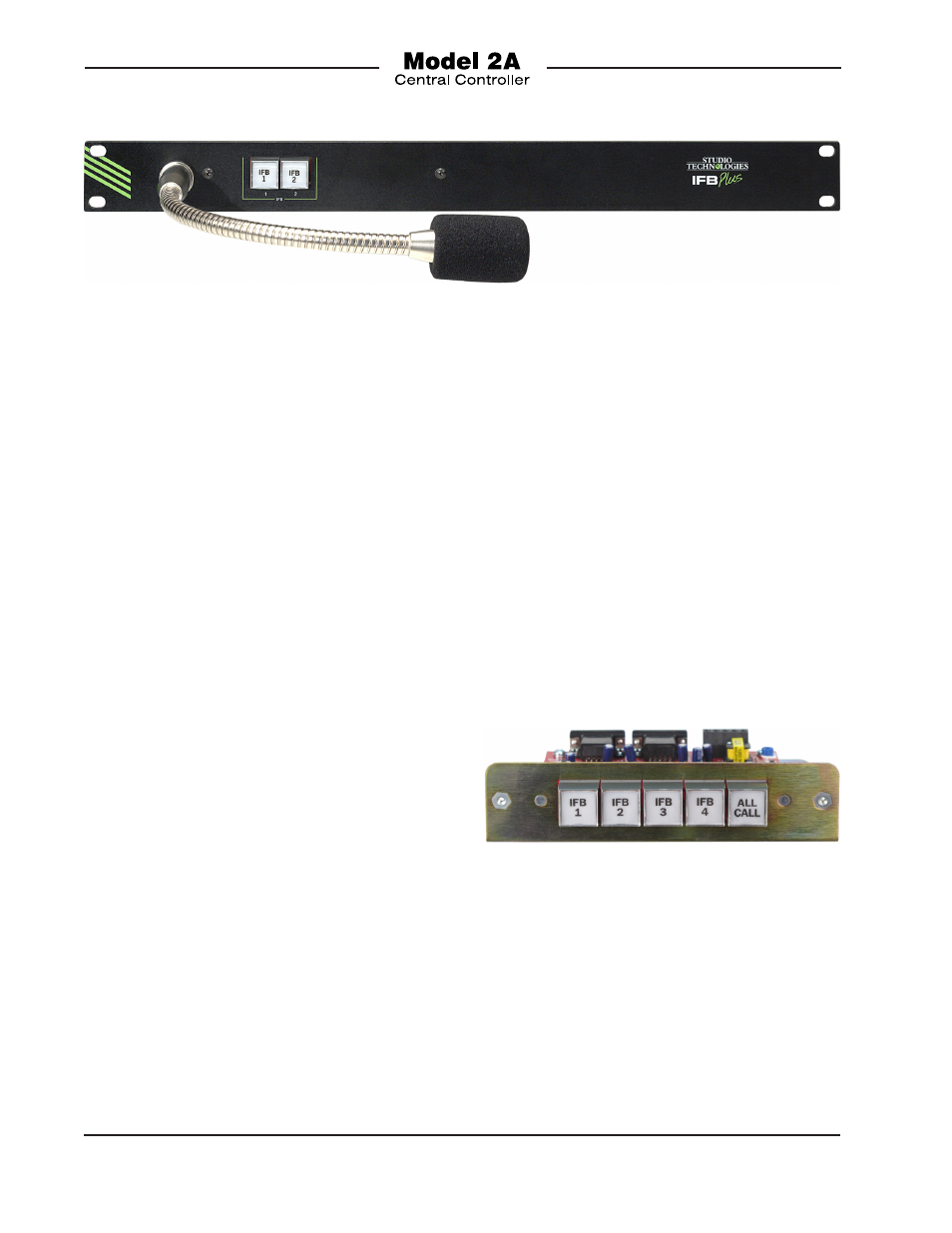
Each of the four IFB channel pushbutton
switches display when an interrupt is taking
place on its respective channel. A fifth but-
ton is specified as “all call” and lights when
pressed. The Model 24 supports connec-
tion of an optional Model 11A Gooseneck
Microphone or a line-level signal. The latter
is transformer-balanced, allowing compat-
ibility with virtually any line-level source. A
switch is used to select the interrupt audio
Figure 4. Model 24 Access Station Front View