Connecting peripherals, Sync connectors – Sierra Video RTR-804 User Manual
Page 15
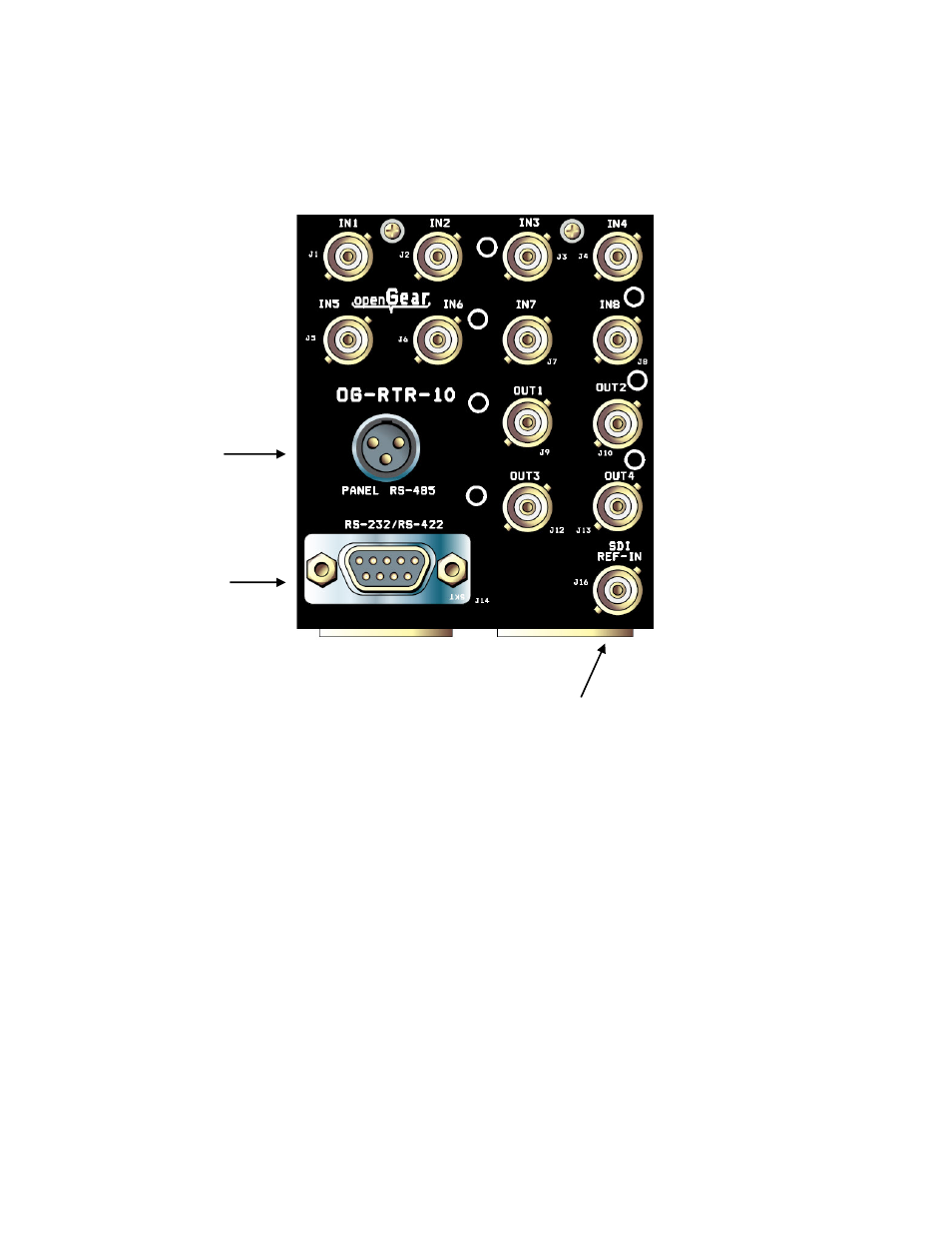
OG-RTR
9
Connecting Peripherals
Control panels and sync inputs are all connected to the rear of the frame. The peripherals
area may vary depending on the model size and type. The OG-RTR-10 and the OG-
RTR-20 have the same connections.
Sync Connectors
There two BNC connectors labeled "REF-1 and REF-2" on the rear of the Open Gear
frame. These are “looping” inputs for sync referencing. Connect either Bi-level or Tri-level
sync to either BNC. If desired, use the second “looping” BNC connector to send to
another device. If the loop is not used, terminate it with 75 ohms.
Selection of “REF-1 or REF-2” is made in the DashBoard software.
If a video sync signal is applied to the routing switcher module, the control system will
cause all switching to occur during the vertical interval of the reference. If no sync is
available, the routing switcher will switch at a random point rather than during the vertical
interval of the reference signal.
Sync adjustments are made via the DashBoard software program (see next section).
RS-232/422
Control connector
Remote Control
Panel
Connector
Connector Not
Used (Future Use)