Channel status indicators: d1 ~ d4, Gpio status indicators: d5 ~ d8 – Sensoray 811 User Manual
Page 12
12
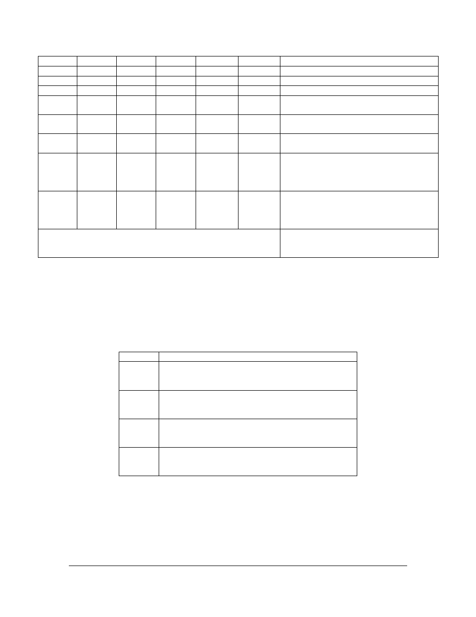
SW2-1
SW2-2
SW2-3
SW2-4
SW2-5
SW2-6
Description
OFF
X
X
X
X
X
Disconnect all digital I/O to TB1~TB4
X
X
OFF
X
X
X
Disconnect all digital inputs from J9
X
X
X
X
OFF
X
Disconnect all digital outputs to J9
X
X
ON
OFF
X
X
Enable connectivity from J9’s digital input
pins to the board (for all 4 channels)
X
X
X
X
ON
OFF
Enable connectivity from the board to J9’s
digital output pins (for all 4 channels)
X
X
ON
OFF
ON
OFF
Enable connectivity for both digital inputs
& outputs from/to J9 connector
ON
ON
ON
OFF
ON
OFF
Enable connectivity for both digital inputs
& outputs from/to J9 connector;
And, route the digital inputs connected to
the TB1 ~ TB4
ON
OFF
ON
OFF
ON
OFF
Enable connectivity for both digital inputs
& outputs from/to J9 connector;
And, route the digital outputs connected to
the TB1 ~ TB4
Others
Reserved
LED
Channel Status Indicators: D1 ~ D4
The LED D1, D2, D3, and D4 can be used for indicating the channel status, respectively.
LED
Signal
D1
Status for Channel-1, the driving signal is connected to
the Channel-1 capturing chipset SAA713xHL’s GPIO15.
A logic low turns the LED on, and a high turns it off
D2
Status for Channel-2, the driving signal is connected to
the Channel-2 capturing chipset SAA713xHL’s GPIO15.
A logic low turns the LED on, and a high turns it off
D3
Status for Channel-3, the driving signal is connected to
the Channel-3 capturing chipset SAA713xHL’s GPIO15.
A logic low turns the LED on, and a high turns it off
D4
Status for Channel-4, the driving signal is connected to
the Channel-4 capturing chipset SAA713xHL’s GPIO15.
A logic low turns the LED on, and a high turns it off
GPIO Status Indicators: D5 ~ D8:
The LED D5, D6, D7, & D8 are used for indicating the status of the digital input/output
signals (pins), labeled as GPIO1 ~ GPIO4 on the board, and directly connected to the
TB1 ~ TB4. A logic 0 (low) turns the LED on and a logic 1 (high) turns it off.