Dip switches, Digital i/o connectors: tb1 ~ tb5, Manufacturing dip switch: sw1 – Sensoray 811 User Manual
Page 11: Digital i/o configuration dip switch: sw2
11
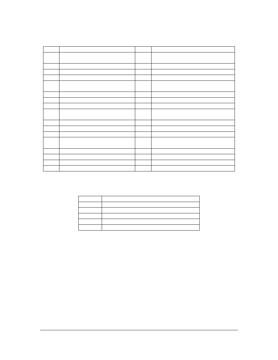
Full A/V (Video & Audio) and Digital I/O Connector: J9
Pin
Signal
Pin
Signal
1
Analog Ground
2
Composite Video In / S-Video In – Y
for Channel-1
3
S-Video In – C for Channel-1
4
Audio In – L for Channel-1
5
Audio In – R for Channel-1
6
Digital Input for Channel-1
7
Digital Output for Channel-1
8
Digital Ground
9
Analog Ground
10
Composite Video In / S-Video In – Y
for Channel-2
11
S-Video In – C for Channel-2
12
Audio In – L for Channel-2
13
Audio In – R for Channel-2
14
Digital Input for Channel-2
15
Digital Output for Channel-2
16
Digital Ground
17
Analog Ground
18
Composite Video In / S-Video In – Y
for Channel-3
19
S-Video In – C for Channel-3
20
Audio In – L for Channel-3
21
Audio In – R for Channel-3
22
Digital Input for Channel-3
23
Digital Output for Channel-3
24
Digital Ground
25
Analog Ground
26
Composite Video In / S-Video In – Y
for Channel-4
27
S-Video In – C for Channel-4
28
Audio In – L for Channel-4
29
Audio In – R for Channel-4
30
Digital Input for Channel-4
31
Digital Output for Channel-4
32
Digital Ground
33
+3.3V
24
Not Used
Digital I/O Connectors: TB1 ~ TB5
TB
Signal
1
GPIO1 – Digital Input/Output for Channel-1
2
GPIO2 – Digital Input/Output for Channel-2
3
GPIO3 – Digital Input/Output for Channel-3
4
GPIO4 – Digital Input/Output for Channel-4
5
Digital ground
DIP Switches
Manufacturing DIP Switch: SW1
The DIP switch, SW1, is used for manufacturing only. Therefore, it is not described in
this manual.
Digital I/O Configuration DIP Switch: SW2
The DIP switch, SW2, is used for configuring Digital I/O routing. Refer to the table
below for the routing details: