Connector signal/pin definitions – Sensoray 811 User Manual
Page 10
10
Connector Signal/Pin Definitions
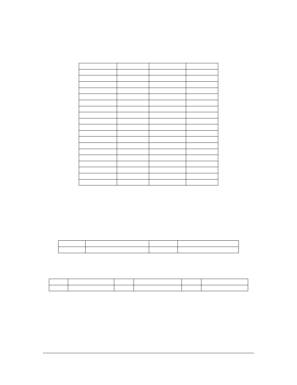
PCI-Express Bus Connector: P1
Pin – Side B
Signal
Pin – Side A
Signal
B1
+12V
A1
PRSNT#1
B2
+12V
A2
+12V
B3
Reserved *
A3
+12V
B4
Ground
A4
Ground
B5
SMCLK *
A5
TCK
B6
SMDAT *
A6
TDI *
B7
Ground
A7
TDO*
B8
+3.3V
A8
TMS *
B9
TRST# *
A9
+3.3V
B10
+3.3VAUX *
A10
+3.3V
B11
WAKE# *
A11
PWRGOOD
( C-Key )
( C-Key )
B12
Reserved *
A12
Ground
B13
Ground
A13
REFCLKP
B14
HSOP0
A14
REFCLKN
B15
HSON0
A15
Ground
B16
Ground
A16
HSIP0
B17
PRSNT#2
A17
HSIN0
B18
Ground
A18
Ground
Note:
*
Not connected.
C-Key Connector Key
Composite Video Input Connector, BNC: J1, J2, J3, and J4
Pin
Signal
Pin
Signal
Inner
Composite Video Signal
Outer/Ring Shield, Analog ground
Stereo Audio Input Connectors, 3.5mm TRS StereoJack: J5, J6, J7, and J8
Pin
Signal
Pin
Signal
Pin
Signal
Tip
Stereo Line-in Left
Ring
Stereo Line-in Right Sleeve
Analog ground