M o tor specifications – Delta 31-750 User Manual
Page 9
9
C O N N E C T I N G S A N D E R TO P O W E R S O U R C E
P O W E R C O N N E C T I O N S
A separate electrical circuit should be used for your tools. This circuit should not be less
than #12 wire and should be protected with a 20 Amp fuse. Have a certified electrician
replace or repair a worn cord immediately. Before connecting the motor to a power line,
make sure the switch is in the OFF position and be sure that the electric current is of
the same characteristics as stamped on the motor nameplate. Running on low voltage
will damage the motor.
W ARNING: DO NOT EXPOSE THE TO O L TO RAIN OR OPERATE THE TO O L IN
D A M P L O C ATIONS.
M O TOR SPECIFICATIONS
Your sander is wired for 110-120 volt, 60 Hz alternating current. Before connecting the
sander to the power source, make sure the switch is in the OFF position. The 3600
RPM motor provides 3600 oscillations per minute.
FASTENING S A N D E R TO A SUPPORTING S U R FA C E
If during operation there is any tendency for the sander to tip over, slide or walk, the
sander must be secured to the supporting surface using the four holes in the base of
the machine. If you purchased the accessory stand, the four plastic feet supplied with
the stand feature holes which allow easy mounting of the stand to a supporting surface.
Fig. 17
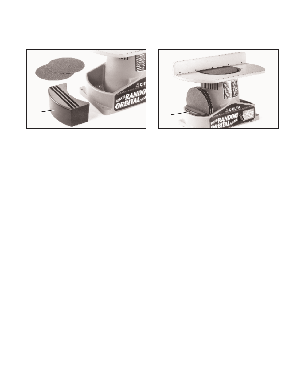
A C C E S S O RY 31-752 DISC H O L D E R
An accessory abrasive disc holder (A) Fig. 16, is available to conveniently store extra
abrasive discs. The disc holder (A) slides neatly into the pocket of the sander as shown
in Fig. 17.
Fig. 16
A
A