Grounding instructions – Delta 31-750 User Manual
Page 10
10
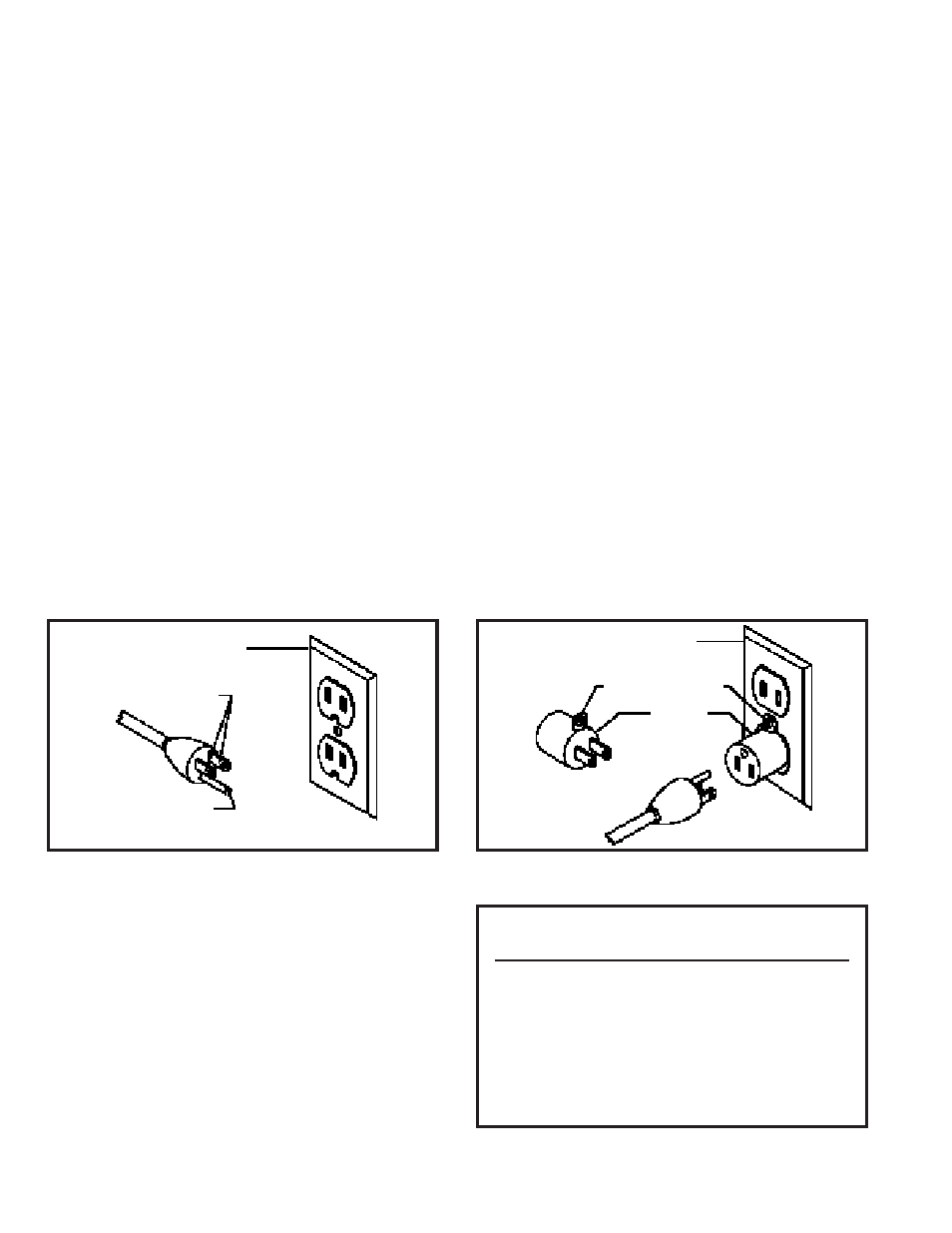
Fig. 19
Fig. 18
GROUNDED OUTLET B O X
C U R R E N T
C A R RYING
P R O N G S
GROUNDING BLADE IS
L O N G E S T OF THE 3 BLADES
GROUNDED OUTLET B O X
GROUNDING MEANS
A D A P T E R
In the event of a malfunction or breakdown, grounding
provides a path of least resistance for electric current to
reduce the risk of electric shock. This tool is equipped
with an electric cord having an equipment-grounding con-
ductor and a grounding plug. The plug must be plugged
into a matching outlet that is properly installed and
grounded in accordance with all local codes and ordi-
nances.
Do not modify the plug provided - if it will not fit the out-
let, have the proper outlet installed by a qualified electri-
cian.
Improper connection of the equipment-grounding con-
ductor can result in risk of electric shock. The conductor
with insulation having an outer surface that is green with
or without yellow stripes is the equipment-grounding con-
ductor. If repair or replacement of the electric cord or plug
is necessary, do not connect the equipment grounding
conductor to a live terminal.
Check with a qualified electrician or service personnel if
the grounding instructions are not completely under-
stood, or if in doubt as to whether the tool is properly
grounded.
GROUNDING INSTRUCTIONS
CAUTION: THIS TO O L MUST BE GROUNDED WHILE IN USE
TO PROTECT THE OPERATOR FROM ELECTRIC SHOCK.
Use only 3-wire extension cords that have 3-prong
grounding type plugs and 3-hole receptacles that accept
the tool’s plug, as shown in Fig. 18.
Repair or replace damaged or worn cord immediately.
This tool is intended for use on a circuit that has an out-
let and a plug that looks like the one shown in Fig. 18.
A temporary adapter, which looks like the adapter illus-
trated in Fig. 19, may be used to connect this plug to a
2-pole receptacle, as shown in Fig. 19, if a properly
grounded outlet is not available. The temporary adapter
should be used only until a properly grounded outlet can
be installed by a qualified electrician. THIS ADAPTER IS
NOT APPLICABLE IN CANADA.
The green-colored
rigid ear, lug, and the like, extending from the adapter
must be connected to a permanent ground, such as a
properly grounded outlet box, as shown in Fig. 19.
CAUTION: IN ALL CASES, MAKE CERTAIN THE RE-
C E P TACLE IN QUESTION IS PROPERLY G R O U N D E D .
IF YOU ARE NOT SURE HAVE A CERTIFIED ELEC-
TRICIAN CHECK THE RECEPTACLE.
Fig. 20
TO TA L LENGTH OF
CORD IN FEET
0 - 25
26 - 50
51 - 100
101 - 150
GAGE OF EXTENSION
CORD TO USE
18 AW G
16 AW G
14 AW G
12 AW G
EXTENSION CORDS
Use proper extension cords. Make sure your extension
cord is in good condition and is a 3-wire extension cord
which has a 3-prong grounding type plug and a 3-pole
receptacle which will accept the tool s plug. When using
an extension cord, be sure to use one heavy enough to
carry the current of the sander.
An undersized cord will
cause a drop in line voltage resulting in loss of power and
overheating. Fig. 20, shows the correct gage to use de-
pending on cord length. If in doubt, use the next heavier
gage. The smaller the gage number, the heavier the cord.