Mdt3f & mdt4f user manual – Scotsman MDT3F12 User Manual
Page 4
To The Installer:
A professional installation of any product is critical
to the long term satisfaction of the user. The ice
maker-dispenser is designed to be installed either
on a counter, or, using a wall hanging kit, hung
from a wall.
Determine the location from the anticipated use
and any options planned for.
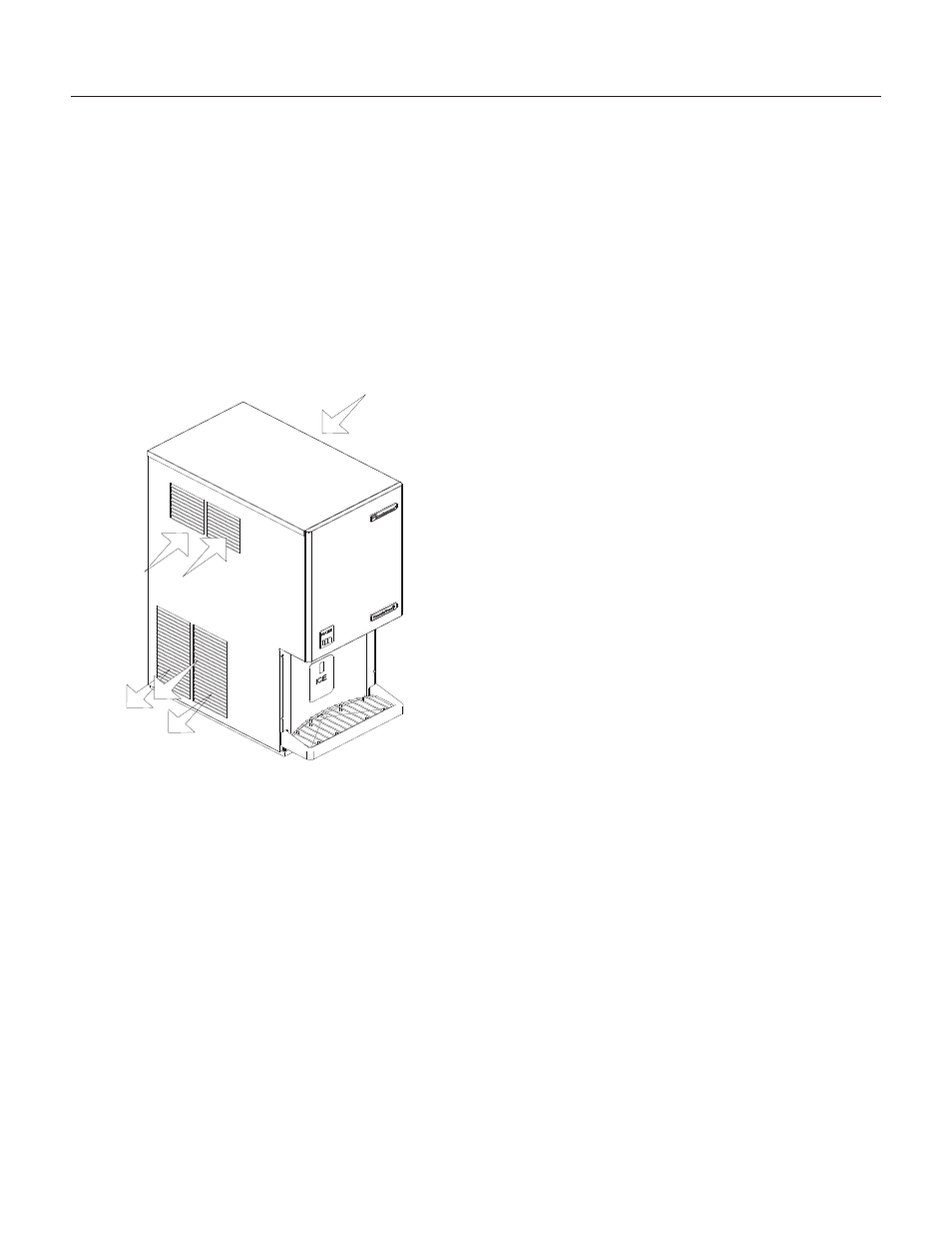
This machine is air cooled and blows air out the
lower left side of the cabinet. Do not install the
machine where the side to side air flow might be
blocked.
The machine will require electrical power, water
and a drain. Follow all local codes. Rough in the
utilities before placing the machine into position
(see For The Electrician and For The Plumber).
Water Quality:
The quality of the water supplied to the machine
will directly affect the purity of the ice and the
reliability of the machine. While the condition of the
water supplied to a building is normally out of the
control of the user, water can be treated at the
point of use.
There are two major types of water impurities:
suspended solids (those that are carried along with
the water and may be filtered out) and dissolved
solids (those that are part of the water and have to
be treated). A water filter is always a good idea,
but does require regular maintenance to change
the cartridge. In some water conditions, water
treatment may be required. Generally this means a
polyphosphate feeder of some kind. Water
softeners are not recommended.
General Installation:
Place the machine in its final location. Remove the
top, right and left side panels:
1. Remove two screws at the bottom of the front
panel.
2. Disconnect wires from water switch.
3. Remove two screws at the front of the top panel.
Lift the top panel and remove it.
4. Remove screws from the sides (top and bottom)
of the side panels and from the splash panel.
5. Pull the side panels back and off the machine.
Plumbing connections may be made thru holes in
the back of the cabinet or thru the base.
·
Route the sink drain to the back of the cabinet.
Route the bin drain to the back panel.
·
Route the electrical power cord from the
junction box inside the cabinet. thru the back
panel .
·
Route the inlet water line thru the back panel or
base to the flare fitting inside the cabinet.
After all plumbing and internal wiring has been
done, replace the side and back panels.
Level the unit front to back and left to right.
The machine does not require sealing to the
counter due to the gasket on the base.
MDT3F & MDT4F User Manual
April 2010
Page 3
Cooling Air Flow
Warm Air
Exhaust
Cooling Air
Flow