Power supply – Datalogic Scanning CBX500 User Manual
Page 7
CBX500
INSTALLATION
MANUAL
7
through the utility program (see the reading device Installation Manual for more details). The reading device
auxiliary interface signals are also available on the internal spring clamp connectors.
After making system cabling and switch settings, connect the reading device to the 25-pin connector on the
CBX500 housing.
Switch ON the CBX500 power switch (see Figure 3). The Power LED turns on (blue) when the power connection
has the correct polarity. The Power LED turns on (red) in case of wrong polarity.
After system functioning has been verified, close the CBX500 using the four cover screws.
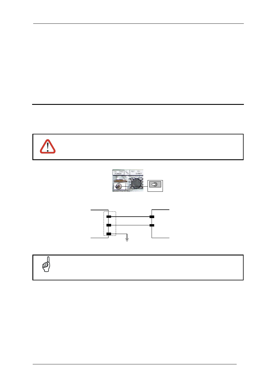
POWER SUPPLY
Power is supplied to the CBX500 through the Vdc and GND pins provided on the spring clamp connector.
The power switch (see Figure 3) switches the power supply ON or OFF for both the CBX500 and the connected
reading device.
CAUTION
The power switch does not control power to the Vdc/GND, +V/-V spring clamps, therefore any
devices connected to these signals (i.e. external trigger, encoder, etc.), are live and are not
protected from polarity inversion. Disconnect the power supply when working inside the
CBX500.
OFF
ON
Figure 3 - Power Switch ON/OFF Positions
CBX500
POWER SUPPLY
GND
GND
Vdc
V+ (10 - 30 Vdc)
Earth
Earth Ground
Figure 4 - Power Supply Connections
NOTE
Vdc is electrically connected to +V, just as GND is electrically connected to -V. This is useful
for supplying external trigger, inputs and outputs from the CBX500 power source, however +V
and -V signals should not be used as power supply inputs to the CBX500.
The power supply must be between 10 and 30 Vdc only.