Mechanical installation, Electrical connections and setup – Datalogic Scanning CBX500 User Manual
Page 6
CBX500 INSTALLATION MANUAL
6
MECHANICAL INSTALLATION
CBX500 can be mounted to various wooden or plastic surfaces using the two self-threading screws (3.9 x 45 mm)
and washers provided in the package.
Mounting to other surfaces such as concrete walls or metallic panels requires user-supplied parts (screws, screw
anchors, nuts, etc). A mounting template is included in the package to facilitate hole drilling alignment.
CBX500 can also be mounted to a DIN rail or a Bosch Frame using the following mounting accessories: BA100
(93ACC1821), BA200 (93ACC1822).
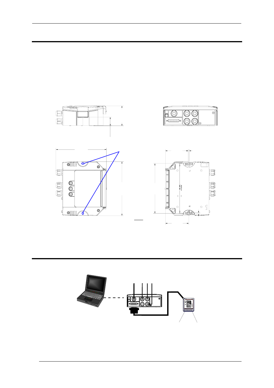
The diagram below gives the overall dimensions of the CBX500 and shows the two mounting through-holes.
178
[
7.01]
82.9
[3.26]
80.9
[3.18]
4
[0.16]
4
[
0.1
6]
71
[2.8]
180
[7.1]
193
[7.6]
30
.7
[1
.2
1]
Figure 1 - Overall Dimensions
ELECTRICAL CONNECTIONS AND SETUP
The following figure shows the typical layout.
Figure 2 – System Layout
The dotted line in the figure refers to an optional (temporary) hardware configuration in which a portable PC can
be quickly connected to the CBX500 (and consequently to the reading device auxiliary interface) through the
internal 9-pin connector. This allows monitoring of the data transmitted by the reading device or configuration
Reading Device
Configuration PC
PWR
Scanner
CBX500
Scanner
Auxiliary
Interface
PS, I/O, Main Interface
Mounting
Holes
mm
in