Installing leak detection cable and spot detectors, Wiring for alarm notifications, Using modbus output – RLE LDRA6 Quick Start User Manual
Page 2: Modifying configuration settings
© Raymond & Lae Engineering, Inc. 2011. All rights reserved. RLE
®
is a registered
trademark and Seahawk™, Falcon™, and Raptor™ are trademarks of Raymond &
Lae Engineering, Inc. The products sold by Raymond & Lae Engineering, Inc. are
subject to the limited warranty, limited liability, and other terms and conditions of sale
set forth at http://rletech.com/RLE-Terms-and-Conditions.html.
5141
2/2011
104 Racquette Drive
Fort Collins, CO 80524
970.484.6510
www.rletech.com
4
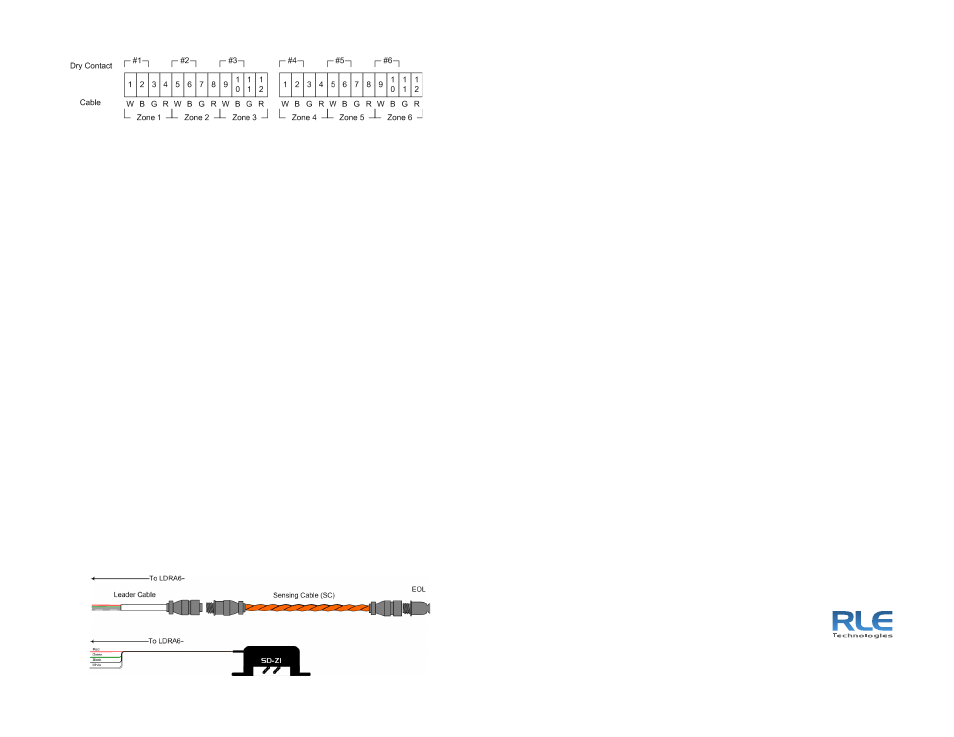
Installing Leak Detection Cable and Spot Detectors
1
Set the desired zone’s switch in the Cable position.
2
Route the SeaHawk leak detection cable (sensing cable) through the
area to be monitored. Use caution when routing the sensing cable
around objects so that the cable does not get damaged.
The cable should lie flat on the floor where it is laid and the area should
be clean to prevent false alarms due to contamination. RLE recommends
the use of SeaHawk J-clips (JC) to secure the sensing cable to the floor.
3
Mount the SD-Z or SD-Z1 spot detector in the area to be monitored. The
spot detector can be mounted with a ram set, mounting studs, or bonding
material (Mastic
®
).
Note: One Leader Cable Kit (LC-KIT), sold separately, is required per zone to
connect the LDRA6 to SeaHawk sensing cable. Spot detectors do not require
a special cable to connect to the LDRA6 panel; use a standard 22/4 conductor
cable to extend the distance to the LDRA6. Contact RLE for distances over
500 feet (152.4m).
4
Connect the cable to a leader cable and an end of line terminator (EOL)
to the end of the cable run.
5
Wire the leader cable to the desired zone to be monitored.
The LDRA6 should have no alarms when the cable is configured and
installed correctly.
6
To test that the cable is registering alarms properly, disconnect the cable,
and verify that a cable break alarm has occurred (yellow flashing alarm).
7
Reconnect the cable, reset the unit, and test the unit for leaks by placing
a damp cloth around the sensing cable.
If a leak alarm occurs (red flashing alarm), the sensing cable has been
successfully installed. For more detailed instructions and installation tips,
refer to the LDRA6 User Guide.
5
Wiring for Alarm Notifications
Wire each relay output to the desired external alarm or building management
system (BMS). The LDRA6 has a general system summary alarm output, and
each zone has an individual relay output.
6
Using Modbus Output
Wire the Modbus output via the EIA-485, twisted-pair wire to the desired alarm
or BMS. For Modbus registers, refer to the LDRA6 User Guide available at
http://www.rletech.com.
7
Modifying Configuration Settings
You can adjust settings for the LDRA6 such as leak sensitivity for individual
zones, LED alarm colors, and Modbus port adjustable settings.
To change these settings:
1
Connect a pass-through cable from your computer to the LDRA6’s Craft
Port (this port is an EIA-232 connection).
2
Use HyperTerminal to access the LDRA6’s configuration options.
For more information about these options, refer to the LDRA6 User Guide
(available at http://www.rletech.com).