RLE F200 User Manual
Page 2
the Setup tab and then click on the Network link. Type the desired address into
the IP address field and click the Save Settings button.
Web Interface
Dashboard
The Dashboard is your main point of contact
for the F200. Accessible from any web
browser or mobile device, the Dashboard
display includes the status of all sensors,
digital inputs, and sensing cables connected
to and monitored by the F200.
As you connect sensors to the F200, their
information appears on the Dashboard.
If you have leak detection sensing cable
connected to the F200, you will need to use
the Inputs tab on the Setup menu to enable
the leak detection monitoring. Then it too will appear on the Dashboard. Other
items that can be configured to display on the Dashboard include digital inputs, a
button to control the relay output, and displays from IP web cameras. Configure
these items on the Sensors, Inputs, and Reporting tabs of the web interface.
Setup Menus
Use the menus in the Setup tab to configure your F200. When you begin typing
changes into any of the fields, they will turn either green to indicate your changes
are acceptable, or red, to indicate your changes cannot be submitted. If a field
turns red, you’ve likely typed more characters than the field can accept, or you’ve
entered a character that can’t be used in that field. Once you delete the excess or
offending character, the field will turn green again.
When you edit a section, a Save Settings button appears at the bottom of that
section. Click this button to save your changes. Changes will neither be saved
nor implemented until you click the Save Settings button.
Network
Use the network tab for settings including the device name, NetBios name, IP
address, primary DNS, and NTP server.
The NetBios name is used to identify resources
on a local network. The default NetBios name
is the F200’s serial number. The F200’s NetBios
name can also be used - only on a local network
- to quickly access the F200’s web interface. Edit
the NetBios name as you’d like - it must be 15
characters or less, in all capital letters. Save your
changes. Then, in the web browser’s address
bar, type rle-netbiosname/ and press enter - but
replace the netbiosname text with the actual
NetBios name of your F200. For example, the
NetBios name of the F200 is SERVERROOM, type
rle-SERVERROOM/ in the address bar. Place a
backslash after the NetBios name. This ensures the browser executes a DNS
lookup instead of a web search. Press enter to access the web interface.
You can choose to use DHCP to obtain an IP address, or to assign the F200 a static
IP. If you choose static IP, fill in the blanks with information provided by your
network administrator and remember to save your settings.
Sensors
Use the sensors tab to configure information, alarm parameters, and alarm
notification (email, audible, activate relay output, etc.) for each 1-wire sensor that is
currently connected to the F200.
Inputs
Leak Detection
The F200 monitors up to 200 feet of leak
detection cable, configured in a single
zone. If you have leak detection
cable connected to the F200 you will
need to use this menu to enable the
leak detection monitoring. Once leak
detection is enabled, the leak detection cable
icon will appear on the F200’s Dashboard.
Use the inputs tab to set the sensitivity for
the cable - if you select high sensitivity,
the F200 will alarm when it contacts a
smaller amount of water. If you select low
sensitivity, the F200 will need to come in contact with a larger amount of water
before it issues an alarm. Then establish notification parameters for a detected leak
or cable break and save your changes.
Digital Inputs
Use the inputs tab to name your digital inputs and to configure alarm and
notification parameters (email, audible, enable relay output, etc.) for each input.
Keep in mind the “When” box will tell the F200 when to send an alarm. For
instance, if your digital input is normally open, the F200 should generate an alarm
when that contact is closed. So for that input, you’d select “Closed” in the When
drop down, and then decide what notification action the F200 should take.
Network Cameras
Want to view your remote facility any time, from anywhere? Use a web camera.
Once you have one installed and running in your facility, you can link to it from the
F200. Enable the webcam capabilities and use the fields to name the camera and
direct the F200 to its streaming image. You can also enter a URL that will take
users directly to the webcam. The F200 can provide views to four cameras. Once
each camera is enabled, it will appear on the F200’s Dashboard.
Reporting
Email Notifications
Use this feature to send email alerts when the F200
goes into alarm. Enable email notifications and
enter the email addresses in the Recipients box.
Recipients will receive all email alerts generated by
the F200.
Once you save any changes made within this
section, a test email button appears. Send a test
email to ensure your notifications are working
correctly, and that your spam filter hasn’t blocked
the incoming email notifications.
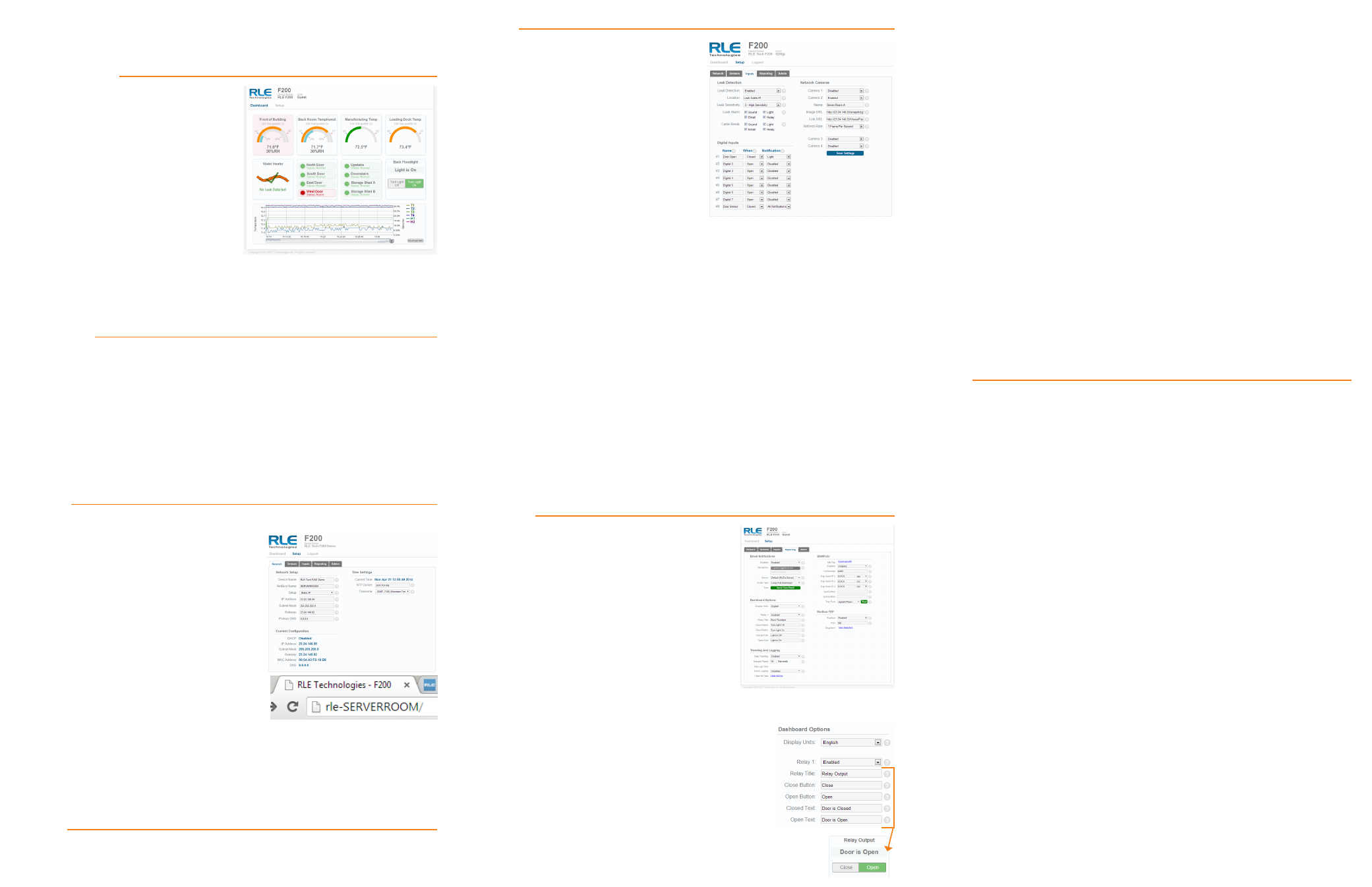
Dashboard Options
Use the Reporting tab to designate English (Fahrenheit) or metric (Celsius) units.
Relay Output
When you enable the relay output, a button to control
the relay output appears on the Dashboard. The button
allows approved users to open and close the relay output
from the F200’s Dashboard. Use the options to configure
the button’s labels. Any alarm condition that is
configured to change the state of the relay output
will override the manual button control of the
relay. If an alarm is active, you cannot turn off the alarm with
the manual relay control button.
Trending and Logging
Once trending is enabled, a graph will appear on the Dashboard. To examine the
points on the graph in greater detail, use your mouse to highlight a section of the
graph and zoom into it, or use the slider bars beneath the graph to adjust the range
of the graph. Double click anywhere on the graph to return to the default view.
The sample period designates the amount of time that passes between logged data
points on the trending graph, and can be set from one second to one day. The
F200 records up to 86,400 points - a shorter sample period records more closely
grouped points for a shorter overall period of time, while a larger sample period
charts data points spaced farther apart, but over a greater overall period of time.
The trending log is downloadable as a CSV file.
Enabling event logging generates a table on the Dashboard that logs all major
alarm events with a date and time stamp, as well as the return to normal date and
time for each event.
SNMPv2 and Modbus TCP
The F200 can be configured to communicate via SNMPv2 and Modbus TCP. If you
wish to use this functionality, configure the settings on this page. Note that links in
these headings allow you to download the SNMPv2 MIB file and to view the current
readings of all the F200’s Modbus TCP registers.
A separate document, available in the Support section of RLE’s website, further
details the F200’s Modbus capabilities.
Admin
Firmware Updates
When you click the Check for Updates button, the F200 will check with RLE to see
if it needs a firmware update. If it does, it will download and install the firmware
on its own, and then reboot itself once the firmware is installed. Once the reboot
is complete, the F200 will be ready to resume its operations. Please be sure not to
access or configure the F200 while it’s downloading and installing new firmware.
System Controls
The reboot button allows users to remotely reboot the F200. Use the Identify
button to make the unit’s LED flash and its audible alarm to sound. This helps
users connect a web interface with an actual physical unit.
Users
Two types of users can be configured on the F200. Up to eight usernames can
be configured in each of the two categories. Each username can be used by only
one user at a time. It is very important for each user to have their own
username:
• Admin User - Admin Users can view and edit the F200’s Setup screens.
• Normal User - Normal (Read Only) Users can only view the F200’s Dashboard.
There are three login configurations:
• Never - Users are never required to log in. Anyone can view the Dashboard
and Setup screens, and anyone can change the F200’s configuration through
the Setup screens.
• To Change Settings - A login is NOT required to view the Dashboard. Only
users logged in as Admin Users can view and edit the Setup screens.
• Always - All users are required to log in. Normal Users can only view the
Dashboard. Admin Users can also view and edit Setup screens.
A relay control checkbox is also located on this page. If you check this checkbox,
only Admin users will be able to operate the Relay button on the Dashboard.
Logout
If you’re logged in to the F200 and have finished your configuration work, click this
link. It will log you out of the device and return the view via your workstation back
to its read-only state.