Leak sensitivity, Test the system – RLE LD1000 User Manual
Page 2
SW 1-4
Alarm Delay Setting - The time between when an alarm is detected and when the LD1000 reports
the alarm. The alarm must be present during the entire delay in order for the alarm to sound.
Off (default)
10 second alarm delay
On
Two minute alarm delay
Leak Sensitivity
Leak sensitivity indicates how much water must be present for the controller to
signal an alarm condition. The lower the sensitivity setting, the more water must
be present to trigger an alarm. Use the pot at R25 to set the sensitivity.
R25
Set the Leak Sensitivity
High
Gently turn the dial clockwise as far as it will go.
Medium (default)
Gently adjust the dial so it is in between the high and low settings.
Low
Gently turn the dial counter clockwise as far as it will go.
Audible Alarms and Status LEDs; Quiet/Reset/Test Button
JMP2 controls the audible alarm. By default, the audible alarm on the LD1000
is enabled - the jumper is placed over the two prongs on JMP2. To disable the
audible alarm, remove the jumper from JMP2.
The LD1000 has three status LEDs:
Status LEDs
Color
Condition
Status Description
Green
Power
The light glows solid green when power is applied to the unit.
Yellow
Alarm -
Cable Break
•
Yellow light blinks when a cable break is detected.
•
Light glows solid yellow once the quiet/reset button is pushed.
•
After the cable break is repaired, the light blinks yellow until the
quiet/reset button is pushed again.
Red
Alarm -
Leak
Detected
•
Red light blinks when a leak is detected.
•
Light glows solid red once the quiet/reset button is pushed.
•
After the leak is cleared, the light blinks red until the quiet/reset
button is pushed again.
Red &
Yellow
Alarm - Low
Input Power
Red and yellow lights alternate blinks when a low input power condition
is present.
Use the push button to silence the audible alarm and to test and reset the
system.
Quiet/Test/Reset Button
Quiet When a cable fault or leak is detected the alarm sounds. Push the button once to silence it.
Reset With no alarm present, press the button momentarily to reset the system. If any alarms
still exist after they are reset, the LEDs will turn on, the audible alarm will sound, and the
relays will activate.
Test
Test the LD1000’s internal components - push and hold the button for one second - the
Fault and Leak LEDs will light and the audible alarm will sound. If the button is held for the
entire test sequence, the LEDs will glow solidly and both relays will activate until the switch
is released. This test sequence also cycles when the unit is powered on.
Test the System
Once the LD1000 is set up, you should test the system. If the LD1000 is
connected to a BMS or NMS, notify monitoring personnel before you test.
To verify the LD1000’s functionality, test three points within the length of sensing
cable - one at the beginning, one in the middle of the length, and another near
the end of the length of cable.
There are a variety of ways to simulate a leak.
• Pour a small puddle of water on the cable while it rests on the floor.
• Dunk the cable in a cup of water.
• Wet a paper towel or rag and wrap it loosely around the cable. This is
popular if the cable is used in pipe applications. Be careful to wrap the wet
cloth loosely around the cable. Do not put pressure on the cable.
Remove simulated leak sources. Return the system to its normal operating state.
To test the cable fault alarm, remove the end-of-line terminator (EOL) from
the end of the sensing cable. This will cause a cable break, which should be
reported appropriately by the LD1000. Once the cable break alarm is verified,
reapply the EOL and ensure the system returns to its normal operating state.
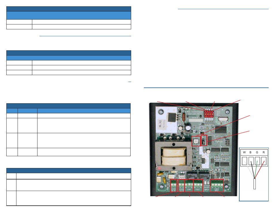
Leader Cable /
Sensing Cable
Input
24VDC
Power Input
Cable
Fault Relay
Output
Leak
Relay
Output
JMP2
Audible Alarm
Jumper On - Enabled
Jumper Off - Disabled
SW1-3
Relay Outputs
Off - Leak & Alarm
On - 2 Summary
24VAC
Power Input
R25
Leak
Sensitivity Setting
SW1-4
Alarm Delay
Off - 10 seconds
On - 2 minutes
SW1-1
Relay Outputs
Off - Non-supervised
On - Supervised
SW1-2
Relay Outputs
Off - Non-latching
On - Latching
Be sure the leader
cable is wired into
the correct pinouts.
Figure A