RLE LD310 User Manual
Page 2
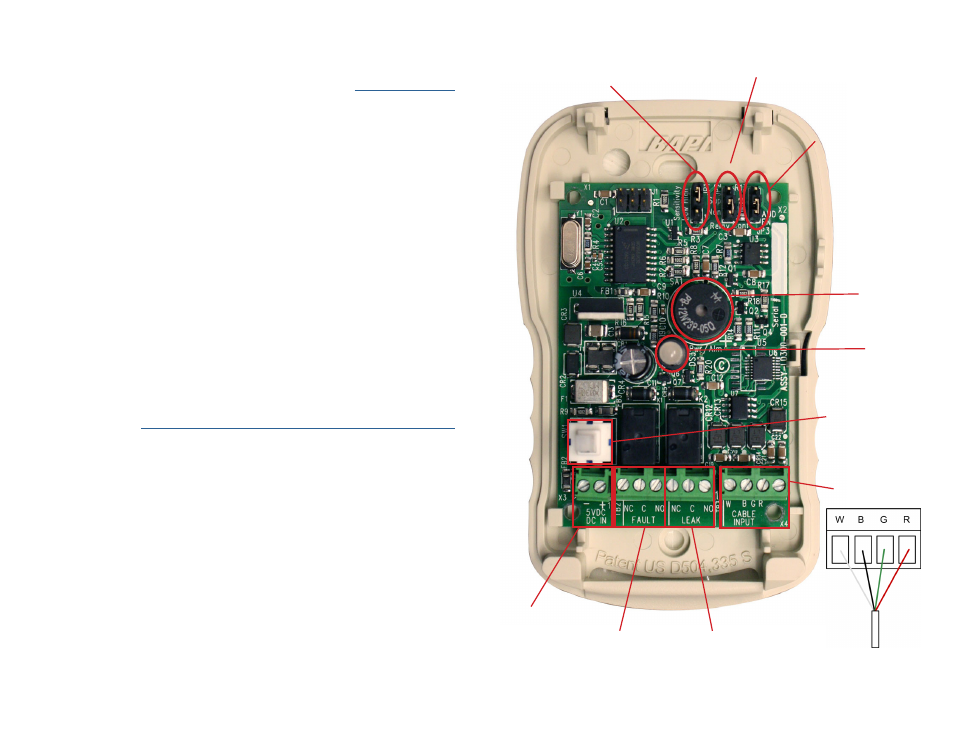
Leader Cable /
Sensing Cable Input
5VDC
Power
Input
Cable Fault
Relay Output
Be sure the leader
cable is wired
into the correct
pinouts.
Leak
Relay Output
JP2
Relay Output Configuration
Top 2 Pins - Supervised
Bottom 2 Pins - Non-supervised
LED
Leak - The LED flashes red while the audible alarm sounds. Once the alarm
silence button is pushed, the LED will continue to display a solid red color until
the leak is resolved and the cable is dry.
Audible Alarm and Silence/Test/Reset Button
By default, the audible alarm on the LD310 is disabled. To activate the audible
alarm, first loosen the screws at the bottom of the enclosure and remove the
unit’s lid. Remove the warning sticker from the top of the audible alarm, move
the jumper on J3 so it covers the bottom two pins, and cycle power to the unit.
Replace the LD310’s lid and tighten the screws to secure it.
The LD310 has one push-button switch, which is used to silence the audible
alarm and to test and reset the system.
The audible alarm sounds when a cable break or leak is detected. When the
audible alarm is activated, push the button once to silence the alarm.
Test mode allows the LD310 to test its internal components. To initiate test
mode, push and hold the button for approximately 5 seconds - when the LED
flashes red and green, the audible alarm sounds, and the relays activate (change
state) the test is complete. Release the button.
When you release the button after the test cycle, the entire unit resets and the
LED returns to green. If there was a leak or cable break present before you
ran the test and that leak or break is still present, the unit will alarm for this
condition again after a few seconds.
Test the System
Once the LD310 is set up, you should test the system. If the LD310 is connected
to a BMS or NMS, notify monitoring personnel before you test.
To verify the LD310’s functionality, test three points within the length of sensing
cable - one at the beginning, one in the middle of the length, and another near
the end of the length of cable.
There are a variety of ways to simulate a leak.
• Pour a small puddle of water on the cable while it rests on the floor.
• Dunk the cable in a cup of water.
• Wet a paper towel or rag and wrap it loosely around the cable. This is
popular if the cable is used in pipe applications. Be careful to wrap the wet
cloth loosely around the cable. Do not put pressure on the cable.
Remove simulated leak sources. Return the system to its normal operating state.
To test the cable fault alarm, remove the end-of-line terminator (EOL) from
the end of the sensing cable. This will cause a cable break, which should be
reported appropriately by the LD310. Once the cable break alarm is verified,
reapply the EOL and ensure the system returns to its normal operating state.
Audible
Alarm
JP3
Audible Alarm
Top 2 Pins - Disabled
Bottom 2 Pins - Enabled
Silence/Test/Reset
Push-Button Switch
JP1
Leak Sensitivity
Top 2 Pins - Most sensitive
No Jumper - Medium sensitivity
Bottom 2 Pins - Least sensitive