Step 12-power port, Step 1-set output resolution, Step 2 input switch – RGBLink VSP 1314 Quick Start User Manual
Page 2: Step11-serial port step 13-power on
VSP 1314 Quick Start
Version1.0
Page 2 of 3
Address:Rm.S603-604,Weiye Building ,Torch Hi-Tech Industrial Development Zone,Xiamen,
Tel: 00865925771197 Fax: 00865925771202
Email: [email protected] http: //www.rgblink.cn
Step 12-Power Port
VSP 1314 use signal power plug and pull for power
up, connect IEC port power line and VSP 1314 power
to start, and it support AC power from 85 to
265V ,which means world wide compatible.
Step 1-Set Output Resolution
Press Menu/Effect , Rotate the knob to select Output
Format ,Press knob to select Output Resolution.
Setting, Select the Output resolution via rotating the
knob, rotate the knob again, Press Menu/Effect to the
homepage.
VSP 1314 support 9 kinds of output resolutions
as following:
1024×768×60Hz,1280×768×60Hz,1280×720×60Hz,
1280×1024×60Hz,1366×768×60Hz,1400×1050×60Hz,
1440×900×60Hz ,1680×1050×60Hz, 1920×1080×60Hz
Output resolution should be the same or bigger than
display system resolution.
NOTE
Step 2
Input switch
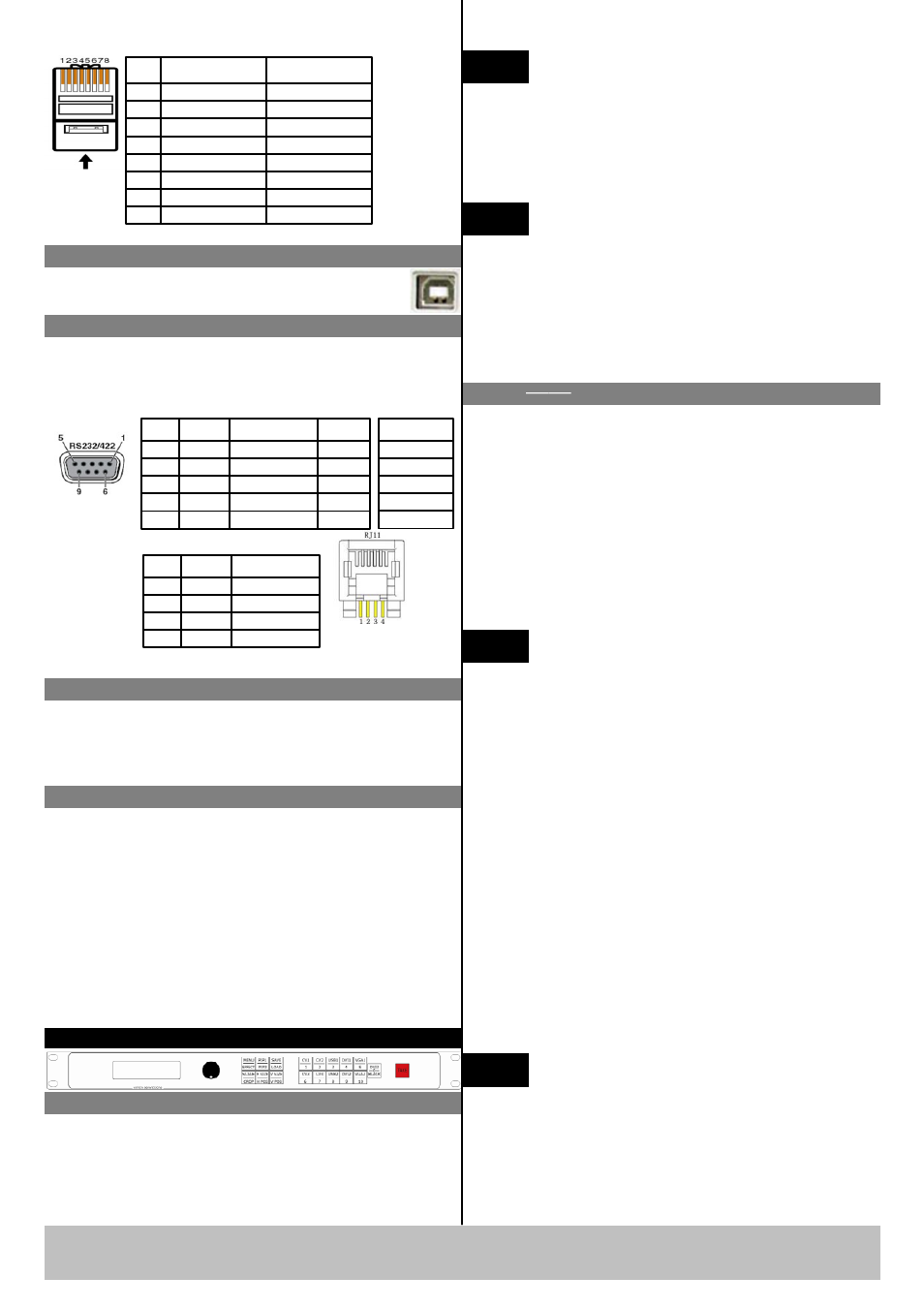
Pin
T568A Wire color
T568B Wire color
1
White-green
White-orange
2
Green
Orange
3
White-orange
White-green
4
Blue
Blue
5
White-blue
White-blue
6
White-orange
Green
7
White-brown
White-brown
8
Brown
Brown
Crossover Cable
CAT5 is
crosswire
standardized
with T568A
for one end
and T568B
for the other.
T568A
T568B
Insert Twisted
Pair Wires RJ-
45 Connector
Pins
Step11-Serial Port
Step 13-Power on
After power , LCD module on the front panel will show
RGBlink and its LOGO, as well as the following
information: AVDSP series VSP 1314, cascadable 3
layers seamless switcher and mosaic scaler. Then come
into work menu homepage, and auto refresh LCD
module menu display statue every two minutes and
display default input signals information and format,
output format. User can operate with VSP1314 with
local front panel and remote control with the software
run on the PC,remote control by RS232,USB or TCP/IP.
Use RS232-to-RJ11 cable to connect a control system
or computer to the back panel RJ11port and the other
end on RS232 port . Below is the definition for RS232-
to-RJ11 cable.
RS-232
Function
2
TX
Transmit
3
RX
Receive
5
GND
Signal Ground
7
---
Not Used
8
---
Not Used
Pin
RS-422
Function
TX-
Transmit(-)
RX-
Receive(-)
GND
Signal
Ground
RX+
Receive(+)
TX+
Transmit(+)
Insert Twisted Pair
Wires RS232/RS422
Connector
Insert Twisted
Pair Wires
RJ11 connector
RJ-11
Function
1
TX
Transmit
2
RX
Receive
3
GND
Signal Ground
4
---
Not Used
Pin
Local Control-Front Panel Operation
Step10-USB Port
USB cable Used to connect the VSP 1314 and
computer.
Default layer 1 is the Program output signal source of
DVI1 ,now the DVI backlight turns green, if signal
keys of the same layer are light off, they cannot be
selected; If users need to change the input signal of
Program, choose signal keys of any other layers. DVI2,
the default signal of layer 2, lights on yellow , it means
Preview outputs DVI2. Other signal keys light on red ,
user selects the signal key as needed, keys will light on
yellow as selected, tap TAKE button to change the
selected signal to Program output.
NOTE
Press TAKE button to change signal between
Program and Preview. About the Menu( Menu/Effect
lights off) tap Menu/Effect, the key lights on green,
tap again to enter Effect page, then the key lights on
red, rotate the knob to select the needed effects of the
model, There are four kinds of effects for user to
select: Wipe Hard, Wipe Soft, FADE, CUT。
NOTE
Function button backlight instructions: the
green light means the upper function, the red light means
the lower function, no light means the function is at the
ready state. Such as press Menu/Effect ,
firstly the green light on and it is the Menu Functional
state, press again and go into Effect functional state with
red light on, press again, light out. And return to the
homepage.
NOTE
Signal source key light instructions::
VSP 1314 Use the traffic light passing control
principle, The green light means in showing: Program
shows the image which green light refers; The yellow
light means to be broadcast; Preview shows the image
which the yellow light refers. The red light means
ready for play, which means that the Preview signal can
be chose; No light means the user cannot work on the
programming.
VSP 1314 supports 4 composite inputs, 2个USB inputs, 2
DVI inputs (compatible HDMI1.3), 2 VGA
inputs(compatible YPBPR), 1 background input (DVI
1.0) , input signal via the corresponding interface. VSP
1314 supports 3 layer display. Layer 1 includes: The signal
source of CV1, CV2, USB1, DVI1, VGA1. Layer 2
includes: The signal source of CV3,CV4,USB2,DVI2,
VGA2. Layer 3 is the background input, User can select
the background signal as DVI3 or the BLACK
background.