Step 8- power port, How to set output resolution, How to add layer power on – RGBLink VSP 3500 Quick Start User Manual
Page 2: Local control-front panel operation, How to edit and define output, Step 7- serial port, How to clear layer, How to scale the layer image, How to crop the layer image, How to set the position of layer image
VSP 3500 Quick Start
Version 1.0
Page 2 of 4
Address: S603~S604, Weiye Building, Torch Hi-Tech Industrial Development Zone, Xiamen, Fujian, China
Tel: 00865925771197 Fax:00865925771202
Email: [email protected]
Step 8- Power Port
Plug in power cord which has IEC connector, VSP
3500 supports AC power from 90 to 264 VAC,50-
60Hz, which means world wide compatible.
How to set output resolution
Press MENU button, and rotate Up/Down knob to
select OUTPUT CONFIG. Press NEXT and rotate
Up/Down knob to select OUTPUT FORMAT. Press
NEXT and rotate Left/Right knob to select OUTPUT
RESOLUTION. Then press NEXT to setup.
How to add layer
Power On
Push power button switcher to ON position. LCD
module on the front panel will show RGBLINK and
VSP 3500 model information, and go into self
verification before it load the last setting configuration
data and send the processed image to the target display
or device. For the first time running, CV1 input is the
default input source.User can operate with VSP 3500
with local front panel and remote control with the
software run on the PC, remote control by RS232, USB
or TCP/IP.
RS-232
Function
2
TX
Transmit
3
RX
Receive
5
GND
Signal Ground
7
---
Not Used
8
---
Not Used
Pin
RS-422
Function
TX-
Transmit(-)
RX-
Receive(-)
GND
Signal Ground
RX+
Receive(+)
TX+
Transmit(+)
Insert Twisted
Pair Wires
RS232/RS422
Connector
Insert Twisted
Pair Wires
RJ11 Connector
RJ-11
Function
1
TX
Transmit
2
RX
Receive
3
GND
Signal Ground
4
---
Not Used
Pin
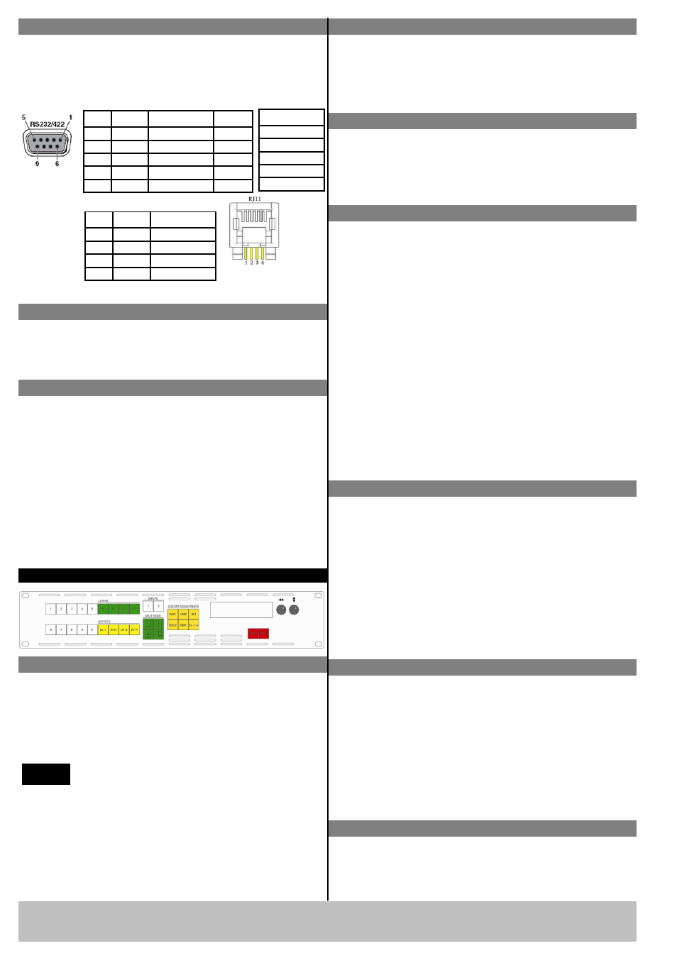
Local Control-Front Panel Operation
In LAYERS area, choose layer that need to increase
layer, that is press any key of layer A, B, C, D (or select
all the 4 keys), key lights, then the layer is selected, and
add layer finished.
How to edit and define output
1. In OUTPUTS part, push DVI1, DVI2, DVI3, DVI4
and it will light to show it is being programmed;
OUTPUTS part DVI1 key is correspond with DVI1;
OUTPUTS part DVI2 key is correspond with DVI2;
OUTPUTS part DVI3 key is correspond with DVI3;
OUTPUTS part DVI4 key is correspond with DVI4;
2. In FUNCTIONS part, push Scale to adjust the size
of image which means to zoom in/out of the image;
3. In CUSTOM ADJUSTMENTS part, push Crop to
crop the image which means to crop the input signal
of the output screen;
4. In CUSTOM ADJUSTMENTS part, push Position
to adjust the position of the corresponding input
image of the layer which means to adjust the
position of output screen.
Step 7- Serial Port
Use RS232 to RJ11 cable to connect a control system
or computer to the back panel RJ11 port and the other
end on RS232 port. RS232 to RJ11 cable as following
definition.
VSP 3500 supports output resolution as
following:
NOTE
1024×768×60Hz, 1280×720×60Hz,1280×768×60Hz,
1280×1024×60Hz,1360x768x60Hz,1366x768x60Hz,
1400x1050x60Hz,1440x900x60Hz,1600×1200×60Hz,
1680x1050x60Hz,1920×1080×60Hz,1920x1200x60Hz,
2048x1152x60Hz;
How to clear layer
1. In LAYER area, press any key of layer A, B, C, D
that need to clear, key blinks,
2. Press the key again, key light is off, and clear layer
finished.
How to scale the layer image
1. In CUSTOM ADJUSTMENTS area, press 【SCALE】
key, key lights, and start the scale function;
2. In LAYER area, press any bright key of A, B, C, D
(light key among layer key is optional), key lights, and
it can be edited;
3. Rotate the up/down knob to adjust window width;
Rotate the left/right knob to adjust window height;
4. Press 【SCALE】 key again, key light is off, and
close the scale function.
How to crop the layer image
1. In CUSTOM ADJUSTMENTS area, press【CROP】
key, key lights, and start crop the layer image function;
2. In LAYER area, press any bright key of A, B, C, D
(keys light are optional ), key lights, and it can be edited;
3. Rotate left/right knob, and choose the menu options;
4. Rotate left/right knob, and adjust the optional value;
5. Press【CROP】key again, key light is out, and close
crop function.
How to set the position of layer image
1. In CUSTOM ADJUSTMENTS area, press 【Position】
key, key lights, and start the set the position of layer
image function;