RGBLink VSP 3600 Quick Start User Manual
Viewsize the world, Vsp 3600 – quick start, Installation and cabling features
VSP 3600 – Quick Start
Installation and cabling features
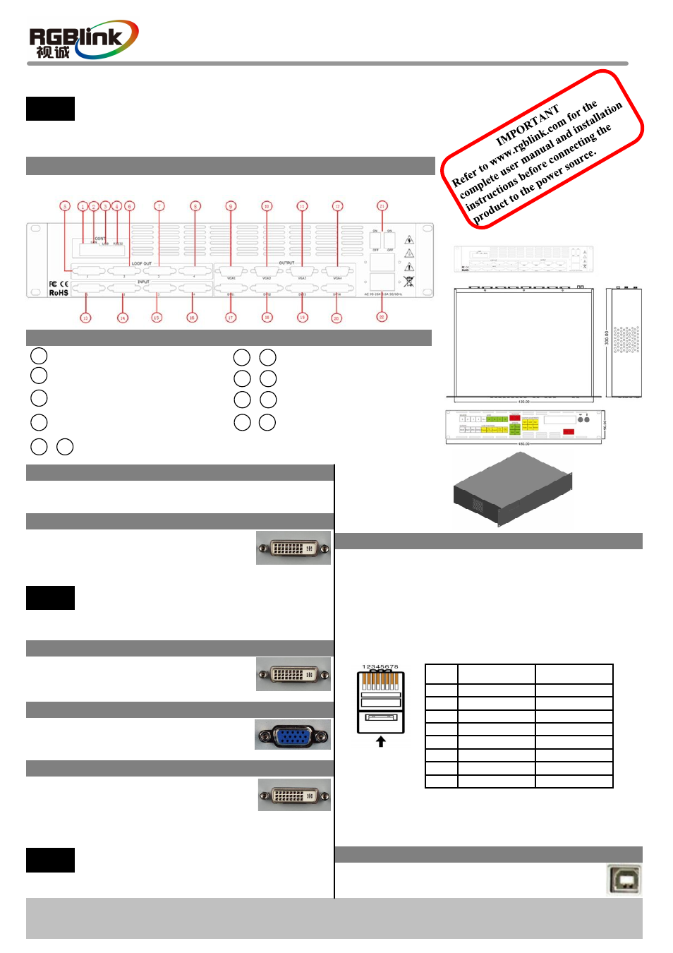
Rear Panel
Connections
10/100M Internet Control Port
9
USB Control Port
2
3
4
12
Power Switch Button
and Power Port IEC-3
Step 1-Mounting
Turn off or disconnect all equipment power sources.
VSP 3600 Quick Start
Version 1.1
Page 1 of 4
Address: S603~S604, Weiye Building, Torch Hi-Tech Industrial Development Zone, Xiamen, Fujian, China
Tel: 00865925771197 Fax:00865925771202
Email: [email protected]
1 Dial switch
RS232 Control Port
21
17
22
DVI Output Port DVI-I
Step 2- DVI Input DVI-I
This guide provides quick start instructions for an experienced installer to set
up and operate the VSP 3600.
DVIinput ports support signal sources
of HDM I from high-definition player
or DVI from PC
Used to connect display system with
DVI input port or LED display control
system; DVI 1 output acts as the default
program output.
NOTE
~
16
13
~
20
VGA Output Port DB-15
DVI Input Port DVI-I
Step 4-VGA Output DB15
Used to connect VGA monitor,
projector or other display system.
Step 5- DVI Output DVI-I
~
NOTE
Comments to use the programs video when
connect with HDMI from high definition
player.
NOTE
Comments to use the sending cards box,
Driver, DV4 from RGBlink for that VSP3600
can not support sending card installed inside.
Pin
End 1
Wire color
End 2
Wire color
1
White-green
White-orange
2
Green
Orange
3
White-orange
White-green
4
Blue
Blue
5
White-blue
White-blue
6
White-orange
Green
7
White-brown
White-brown
8
Brown
Brown
Crossover Cable
CAT5 is wired as T568A at one end and T568B at the
other(Tx and Rx pairs reversed) is crossover.
T568A
T568B
Insert Twisted
Pair Wires
RJ-45
Connector
Pins
Step 7-USB Port
Step 6- Lan Control Port
Use twist CAT5 cable to connect to LAN port, operator
can control VSP 3600 based on default IP address:
192.168.0.100. Operator can also change the IP address
by RS 232 or USB.
Twist CAT5 should be one end in T568A, and another
end in T568B standard.
Use USB cable to connect the VSP 3600 and
computer.
For full installation, configuration, and operation details, refer to the
VSP 3600 user manual, which is available at
VIEWSIZE THE WORLD
5
8
~
DVI Loop Out
Step 3- DVI Loop Out
Can connect the next level VSP 3600
or the device with DVI loop out.