Step 3-setup splice, Step 4-add display window, Step 5-select inputs – RGBLink MVP 320 Quick Start User Manual
Page 2: Step 6-display modes management
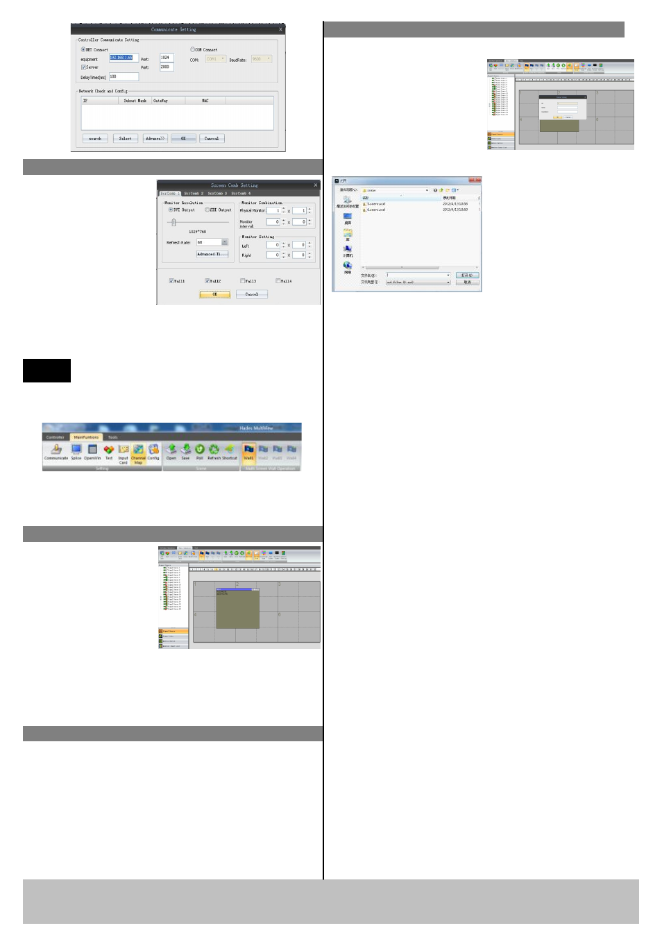
Step 3-setup Splice
Output setting: Splicing
setting is divided into
four groups, which can
separately set output
resolutions and screen
combination types; the
default screen interval is
0. For example, the
splicing of the right
figure is set at 1, the output resolution is 1920X1080,
and combination type is 3X4.
Note
After setting the combination type and
resolution, the following operation should
be carried out.
Step 4-add display window
In the grey zone of the
controlling software,
press the left mouse key
and drag on the
intended output screen
to cover the whole
current screen. And the
below interface will be displayed. A window can be
opened by the shortcut key of “new opened window”,
then double click the left signal source to be shown on
the window.
Step 5-select inputs
User can select input source to the display window by
click on the Signal Source list on the left, after click,
the input will go to the window and display on the
output.
MVP 320 can support multi modes saving and load.
After the set the window
location, size, and input
source, click the save button
to save the file, and type the
file name, then click the
“save”; re-select “open” and
If the scene needs to be
called, the user can select
the needed scene in
“scene”. The scene can
be polled and time
interval can be set.
Step 6-display modes management
MVP 320 Quick Start
Rev 1.1
Page 2 of 2
Address:S603-604 Weiye Building Torch Hi-Tech Industrial Development Zone Xiamen,Fujian Province, P.R.C
Tel: 00865925771197 Fax:00865925771202
Email: [email protected]
Click “Channel Mapping” in the “Main function area”.
After setting splicing, “Reset” must be clicked, which
may take some time and progress bar will appear
during the course, click “Confirm” after finished.
the saved setting will be shown in the menu.