Remko, Way switching valve dn 40, Operation – REMKO DN 40 User Manual
Page 4
4
REMKO
3-WAY SWITCHING VALVE DN 40
Functioning of Inverter heat-pump
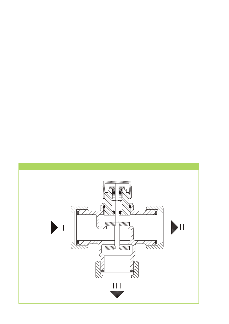
At REMKO the flow direction I must be
open to II in resting position of the 3-way
switching valve. This corresponds to the
heating flow direction. When th actuator
is energised (brown-coloured wire), the
valve moves in position I - III (e.g. HW
preparation). It is vital to check that
the axis and the actuator of the 3-way
switching valve are in the right position
before installation. In the lower figure
you can see the correct position of the
axis and the actuator. If the part which
you have on hand does not match this
figure precisely, proceed according to
Operation
Three-way valve cross-section in an energised state
the modification instructions (text)
of the lower figure.
The flow direction of I to II corresponds
to the hot water charging position
or cooling mode when used
as a "cooling" switching valve in a 4-pipe
system.
The reversal between the two flow
directions takes approx. 7 seconds.
Ele
ktri
sch
e
r
Roh
ran
leg
e
r
egl
e
r
Rüc
ksc
hla
gve
ntil
Art
.-N
r
. 1
07
20
06
Tem
per
atu
r
r
egl
er
Art.
-N
r
. 1
14
28
6
1
„Tr
i-D
TR“
D
r
eiw
ege
-
Ver
teil
ven
ti
l
Massenstrom
qm
[kg/h]
D
ru
ck
ve
rlu
st
p
[m
b
ar
]
D
ru
ck
ve
rlu
st
D
N
0
2
2
D
N
5
N
0
D
4
Legend for REMKO hydraulic diagram
Position AB = I
Position B = II
Position A = III