Electrical connection – REMKO DN 25 User Manual
Page 7
7
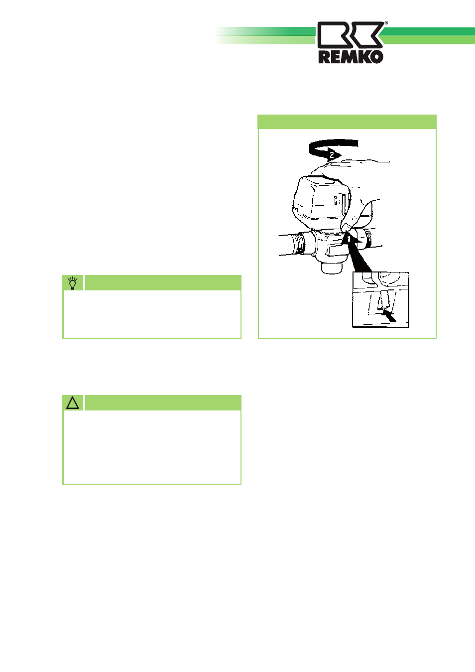
4. Fit the replacement actuator. To do
this, proceed in the opposite order to
removal.
Please note that if the actuator is to be
installed at a right angle to the valve
body, the latching mechanism with not
work.
Installation may only be performed
by authorised specialists.
NOTE
Removing the servo motor
!
CAUTION
All electrical installation work is to
be performed by specialist compa-
nies. Disconnect the power supply
when connecting the electrical ter-
minals.
Electrical connection
Mode of operation
The three-way switching valve is actu-
ated externally via a single pole.
If there is a demand for hot water, the
control system closes the N contact,
which supplies the relay, which then in
turn closes the NO contact (microswitch
C3).
This closes path "B" and opens path
"A".
When path "A" is fully open, this closes
the cams of microswitch C1 and opens
microswitch C2.
At the end of the demand for hot water,
the N contact is opened by the control
system, meaning that the supply to the
relay stops and the NC contact (micros-
witch C3) is closed.
This closes path "A" and opens path
"B".
As soon as path "A" is fully closed, the
cams close microswitch C2 and open
microswitch C1. The three-way switch-
ing valve is ready for the next period of
hot water demand.