REMKO VRS 20 INOX User Manual
Page 8
8
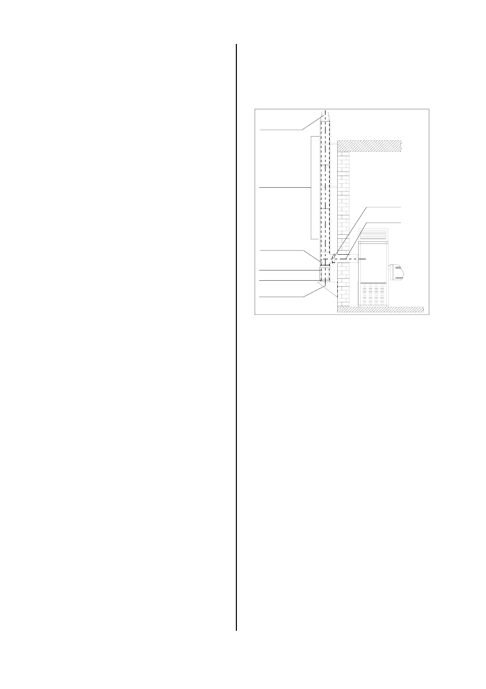
Examples of Use
◊ Double-sided exhaust system / stainless-steel /
outside assembly.
AS-1000-E
AS-ÜGI-D
AS-ME-D
AS-1000-D
AS-T90°-D
AS-RT-D
AS-GI-D
AS-WK-D
Heating Oil Connection
Make sure that there is an adequate supply of fuel.
◊ The installation of the heating oil supply may only be
performed by authorised personnel in line with the
local regulations for oil-fired warm air generators.
◊ Particularly for heating oil lines, make sure that the
cross-section of the lines corresponds to the suction
height, the total line resistance and increased vis-
cosity at lower temperatures and, if necessary, it is
possible to connect an oil transport device.
◊ The suction line must be equipped with a valve at
the end of the hose in the tank.
◊ Even when outside temperatures are low, a suffi-
cient amount of heating oil must be able to flow
freely. Paraffin can accumulate at temperatures
starting at approximately 5 °C depending on the
quality of the heating oil.
Appropriate measures must be taken to prevent this
from happening.
When planning for the exhaust system, please observe
the following:
◊ The exhaust system must be installed and assem-
bled properly and in accordance with the relevant
regulations.
◊ The dimensions of the exhaust lines must be adjusted
to the capacity of the unit and the construction height.
◊ The dimensions of the exhaust systems must ensure
that the exhaust is expelled to the outside regardless
of the operating conditions and guarantee that no
positive pressure is produced in the rooms. These
dimensions are based on the cross-section and
height, and to the extent required, the heat penetra-
bility resistance and internal surface.
◊ The exhaust system openings must stick out at least
40 cm beyond the top of the roof or be at least 1 m
away from the surface of the roof.
◊ If impact pressures, e.g. from fall winds or
neighbouring buildings, are anticipated, the top of
the chimney should be shaped accordingly.
◊ In roof structures, the exhaust system must be led
through a pipe casing or a chute to allow the ex-
haust line to expand when heated.
◊ The unit connection must be impermeable and se-
cured with rivets or screws from becoming acciden-
tally loose.
Burner Installation
The forced-air burner supplied by the manufacturer is
attached to the front of the unit with a clamp flange.
You must observe the following:
◊ Only forced-air burners with automatic burners that
have a 5 sec. safety period may be used.
◊ The burner must be adjusted to the full heat load of
the unit.
◊ The combustion chamber may not be operated be-
low capacity.
◊ The exhaust temperature may not fall below 160 de-
grees Kelvin above the room temperature.
Condensation accumulation.
◊ Follow the operating instructions of the burner sup-
plied by the manufacturer.
◊ If burners from other manufacturers are used, they
must be checked for compatibility with the unit.
Fan Motor Connection
The units are completely wired at the factory.
If modifications are made or the fan motors are re-
placed, make sure that the motor is properly connected.
Exhaust Connection
The exhaust connection must be made properly in ac-
cordance with the relevant regulations.
◊ Proper exhaust expulsion must be ensured.
◊ The exhaust connection may only be made to a pre-
viously approved exhaust system.
*
Installation of an exhaust system always requires
a permit.