Wiring diagram – REMKO VRS 20 INOX User Manual
Page 13
13
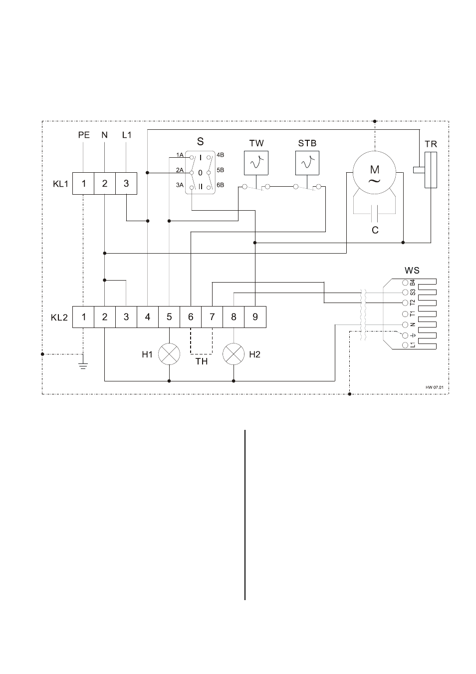
Wiring Diagram
Power supply:
230 V / 1~, N, PE
Fan motor:
230 V / 1~, N, PE
Burner motor: 230 V / 1~, N, PE
We reserve the right to make modifications in dimensions and construction in the interests of technical progress.
An easily accessible emergency switch must be at-
tached in the setup room, but not close to hazardous
areas.
This switch must be protected from damage and un-
authorised use!
*
The electrical connections should only be made by
authorised personnel.
C Capacitor
(Fan)
H1
Control lamp, green (in operation)
H2
Control lamp, red (burner malfunction)
KL1 Terminal strip (power supply)
KL2 Terminal
strip
M Fan
motor
S Operating
switch
STB Safety temperature limiter
TH
Optional: Room thermostat or day/night regulator
TR
Fan control thermostat
TW Temperature
monitor
WS Wieland
plug
Optional