Maintenance and service – REMKO VRS 20 INOX User Manual
Page 10
10
Cleaning the Combustion Chamber and the Heat-
Exchanger
Option I: (in the unit / where the unit is located).
1. Separate the
exhaust connection from the
unit.
2. Disassemble the rear lining plate.
3. Disassemble the inspection cover 2.
4. Remove the flue gas brakes 4 from the heat-
exchanger lines and clean the flue gas brakes.
Replace them if necessary!
5. Clean the combustion residue 4 from the heat-
exchanger lines with a suitable cleaning brush.
6. Disassemble the burner with burner flange.
7. Clean the combustion residue from the furnace
through the burner opening.
A special cleaning set for the REMKO industrial vac-
uum cleaner can be purchased as an accessory.
8. Check the seals of the inspection cover 6 and the
burner flange, replace if necessary.
1
2
3
4
5
6
7
*
After maintenance work is complete, conduct an
electrical safety test.
◊ Dust and dirt must be cleaned from the unit including
from the heat-exchanger, combustion chamber and
forced-air burner. Combustion residue in the com-
bustion chamber and in the heat-exchanger must be
removed.
◊ The V-belt tension and the motor mount must be
checked on a regular basis.
◊ Parts that wear out, e.g. flue gas brakes, oil nozzles,
oil filter inserts, seals etc. must be checked, cleaned
and replaced if necessary.
◊ Make sure to comply with waste gas emission limits
in accordance with regulations.
Maintenance and Service
The operator must have the unit checked and serviced
as necessary, at least once a year, by a representative
of the manufacturing company or another authorised
individual in accordance with the operating conditions.
*
Adjustments or maintenance work on the unit or
forced-air burner may only be performed by
authorised personnel!
*
Prior to doing any maintenance or repair work on
the unit, unplug it from the power supply. It is not
adequate to switch off the unit with the operating
switch!
Important Information on Servicing the Unit
◊ If the cleaning and burner adjustment intervals are
not observed, the guarantee becomes null and void.
◊ It is therefore absolutely necessary to keep records
that work has been performed by authorised person-
nel in addition to creating standard protocols.
◊ We recommend entering into a maintenance con-
tract for the regularly scheduled maintenance and
service work.
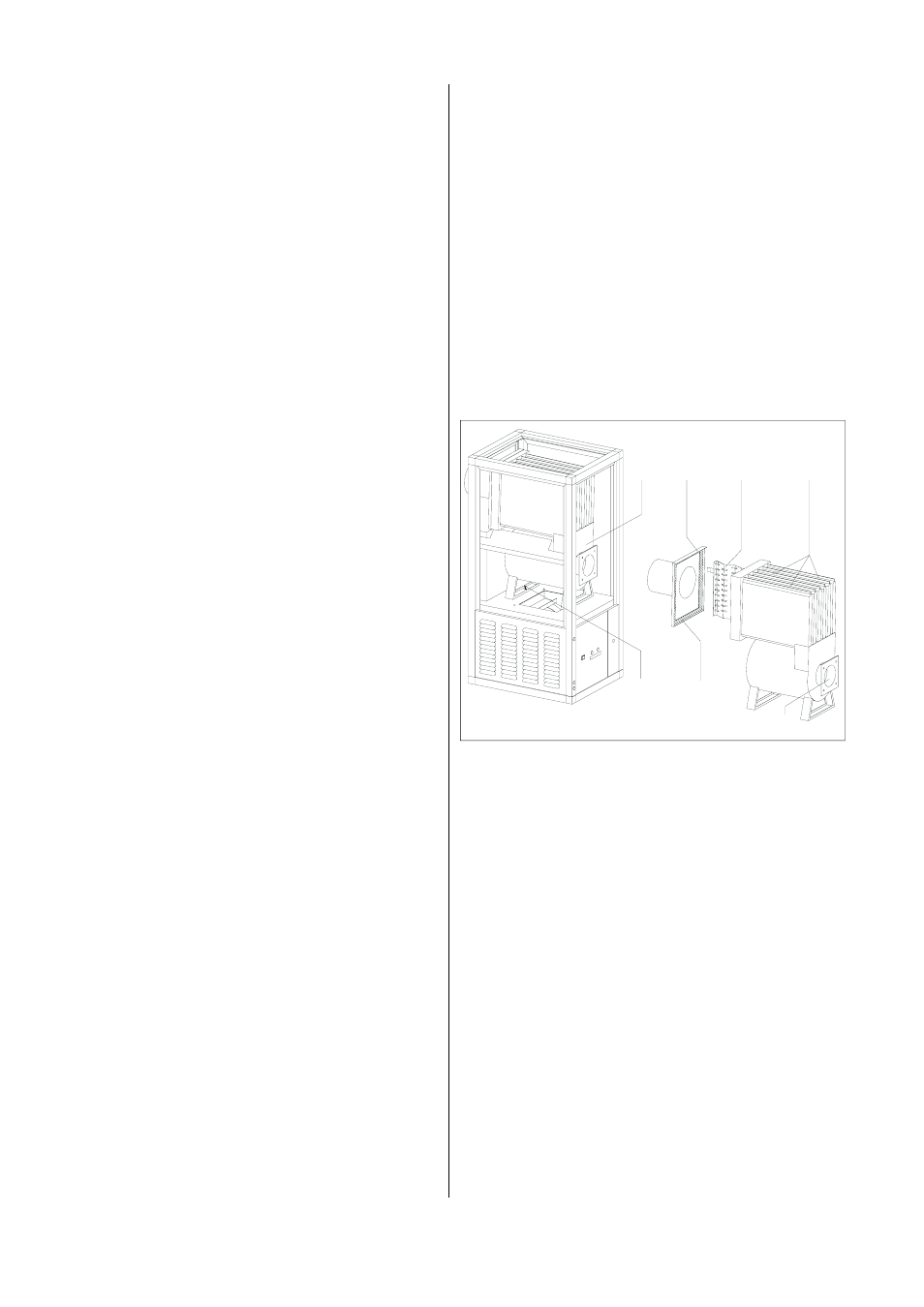
Option II: (outside the unit)
The complete burner chamber 1 can also be removed
from the unit for cleaning.
1. Follow steps 1 and 6 as described in “Option I”.
2. Disassemble the front and top lighting plates.
3. Remove the locking screw 5 on the burner chamber
connection.
4. Pull the entire burner chamber out from the front.
5. Perform the cleaning work as described in “Option I”,
steps 3 to 5 and 7 in a suitable location.
6. Check the seals of the inspection cover 6 and the
burner flange, replace if necessary.
◊ Depending on the assembly option, carefully reas-
semble all of the dismantled parts again correctly in
the reverse order.
◊ Replace any damaged or deformed parts.
◊ Perform maintenance on the burner in line with
manufacturer specifications.
◊ Check all regulating mechanisms and the burner to
ensure that they are working properly.