Wiring diagram htk 100 – REMKO HTK 100 User Manual
Page 12
12
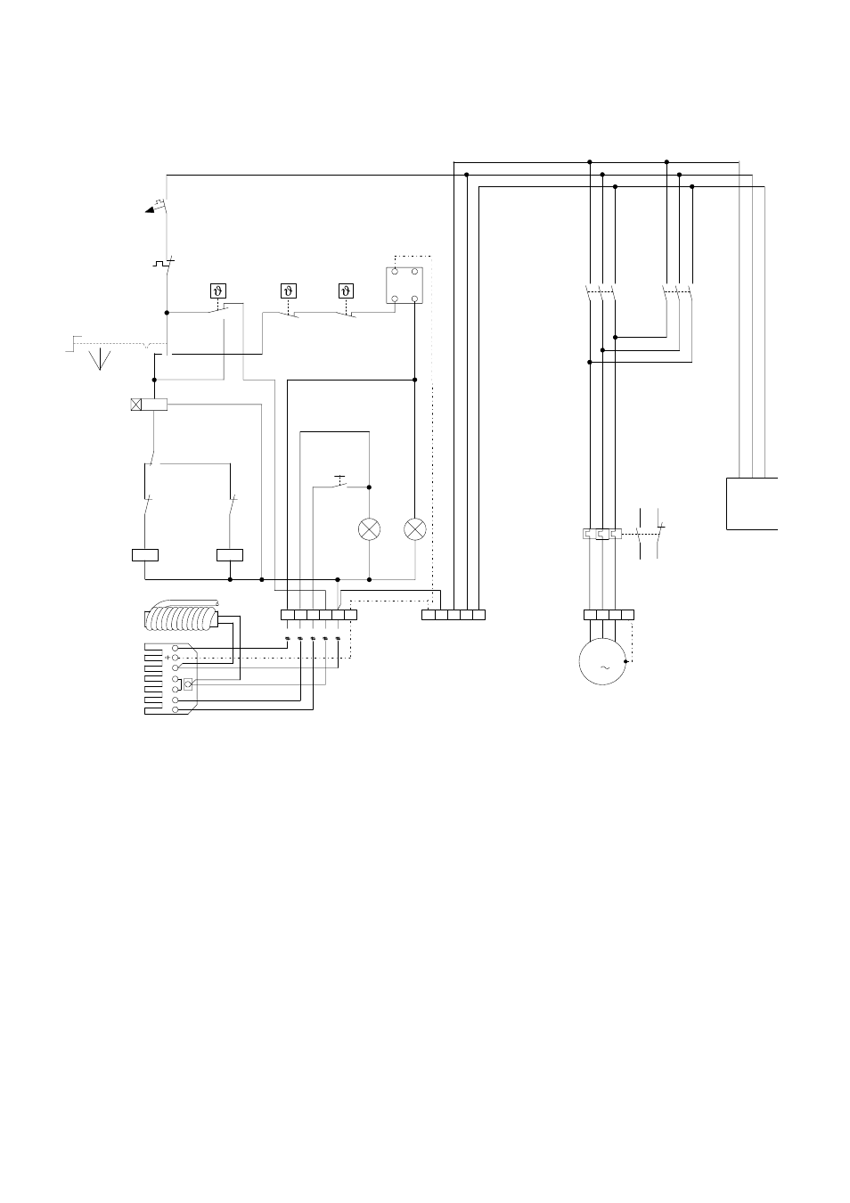
Wiring Diagram HTK 100
Legend HTK 100 and HTK 160
S1 = operating switch
S2 = external reset button (burner)
H1 = control lamp, green (in operation)
H2 = control lamp, red (burner malfunction)
TR = fan control thermostat
TW = temperature monitor thermostat
STB = safety temperature limiter
X1 = terminal strip
M = fan motor
WS = plug to burner, 7-pole
RT = room thermostat socket
ÖV = oil preheater
97
98
M
3
PE
L1 L2 L3
N
L1 L2 L3
U
V W PE
5
3
6
4
1
2
5
3
6
4
1
2
1K8.1
1K7.1
1K5.1
X1
X1
95
96
95
96
1F3.1
1Q3.1
Aus
Lüf
te
n
Hei
zen
S1
2
4
1+3
1K7.2
1K5.1
1K8.1
12
14
11
21
22
1K7.1
1K7.1
21
22
1K8.1
1
2
3
4 N PE
X1
TW
STB
TR
3
2
1
PE
RT
H1
H2
S2
L1
N
T1
T2
S3
B4
ÖV
WS
1Q3.1
1
3
4
5
2
control circuit
load circuit
Legend only HTK 100
1F3.1 = controller fuse
1Q3.1 = motor protection relay
1K5.1 = phase sequence relay
1K7.1 = main contactor
1K7.2 = time relay
1K8.1 = main contactor
Heat
ing
OFF
V
ent
ila
tion