Remko rm – REMKO RM Series User Manual
Page 18
200
120
1500
120
120
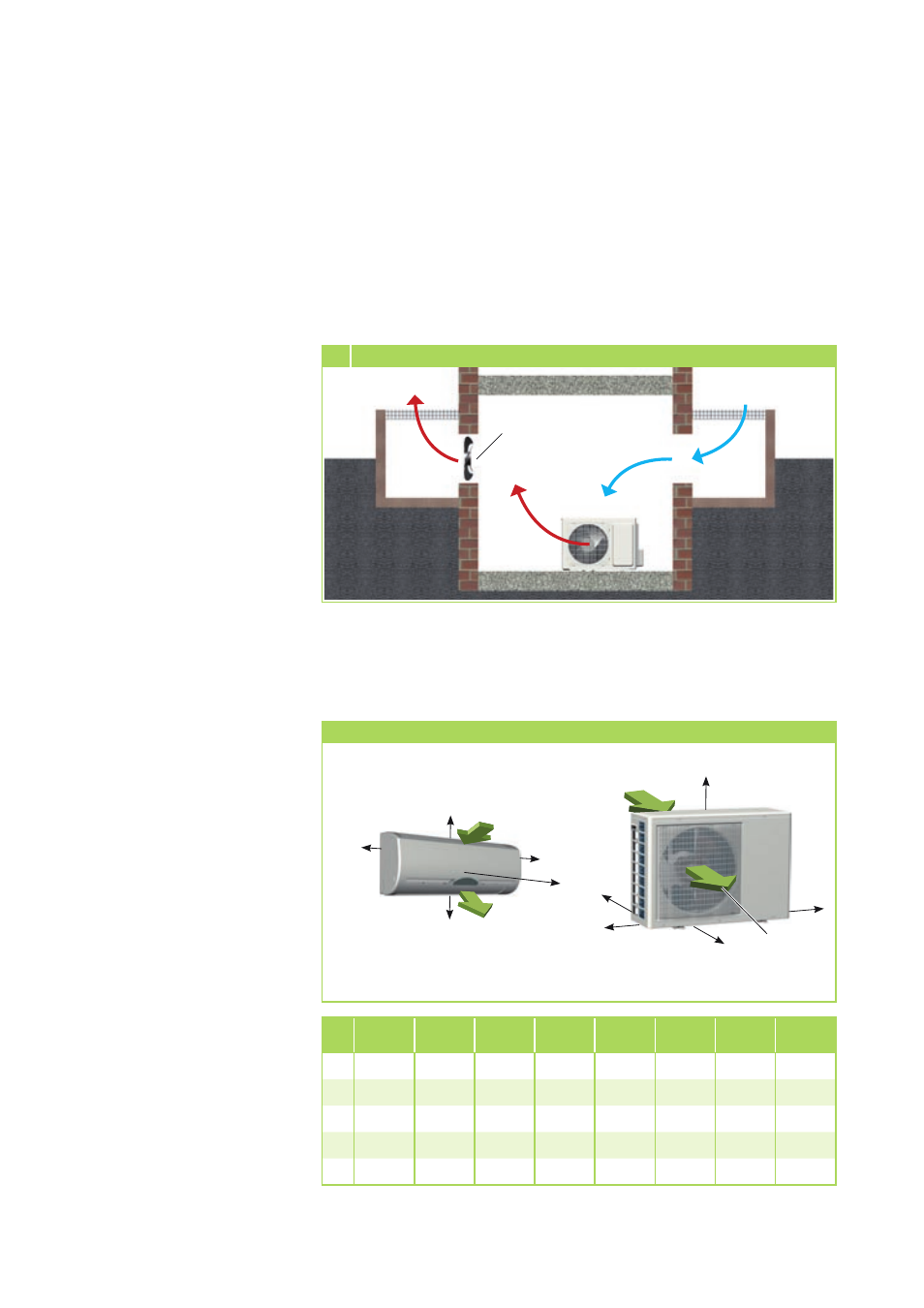
Installation inside buildings
■
Ensure there is adequate heat
dissipation when placing the
outdoor component in cellars,
attics, adjoining rooms or halls
(Fig 5)
.
■
Install an additional fan with
a rated flow comparative to
that of the outdoor component
being installed in the room.
This is used in conjunction with
ventilation ducts to compensate
any pressure losses (Fig 5).
■
Ensure a continuous and
unobstructed air flow from
outside, preferably using
sufficiently large air intakes placed
opposite each other (Fig 5).
■
Comply with any regulations
and conditions affecting
the statics of the building.
If necessary, fit acoustic
installation.
Minimum clearances
Warm air
Fresh
cold air
Light
well
Outdoor unit
Warm air
Light
well
Additional
fan
5 Installation inside buildings
Air intake
Air outlet
All values in mm
Minimum clearances
The adjacent illustration specifies
the minimum clearances required
to assure trouble-free operation of
the equipment.
These protection zones serve
to ensure unobstructed air flow
through the inlet and outlet
and provide sufficient space for
effecting maintenance and repairs
whilst also protecting the unit
against damage.
Air intake
Air outlet
E
D
C
A
B
RM
226 AT
RM
235 AT
RM
252 AT
RM
268 AT
RM
326 AT
RM
335 AT
RM
426 AT
RM
435 AT
A 200 mm 200 mm 200 mm 200 mm 200 mm 200 mm 200 mm 200 mm
B 1300 mm 1300 mm 1500 mm 1500 mm 1500 mm 1500 mm 1500 mm 1500 mm
C 500 mm 500 mm 600 mm 600 mm 600 mm 600 mm 600 mm 600 mm
D 150 mm 150 mm 150 mm 150 mm 150 mm 150 mm 150 mm 150 mm
E
500 mm 500 mm 500 mm 500 mm 500 mm 500 mm 500 mm 500 mm
REMKO RM
18