Welding cable selection table – Profax PRO II x User Manual
Page 11
®
®
®
®
9
8
Charts & Tables
Section 4
Charts & Tables
DRIVE ROLL, KIT AND GUIDE CHART
RC 1 PIN REFERENCE
INTERCONNECTING & EXTENSION CORDS
PRO
IIx
PRO
IVx
WIRE DIAMETER
KIT NO.
KIT NO.
TYPE
DRIVE ROLL INLET GUIDE
OUTLET GUIDE INTER. GUIDE
.023/.025(.6mm )
9095x
9110x
V
9054
9070
9085
9131
.030
(.8mm )
9095x
9110x
V
9054
9070
9085
9131
.035
(.9mm )
9096x
9111x
V
9055
9071
9086
9131
.045
(1.2mm )
9097x
9112x
V
9056
9071
9086
9131
V - KNURLED
.030
(.6mm )
9098x
9113x
VK
9057
9070
9085
9131
.035
(.8mm )
9099x
9114x
VK
9057
9071
9085
9131
.045
(1.2mm )
9100x
9115x
VK
9058
9071
9086
9131
.052
(1.4mm )
9101x
9116x
VK
9059
9072
9087
9131
1/16 in. (1.6mm )
9101x
9116x
VK
9059
9072
9087
9131
PRESSURE ROLLS
FLAT
SMOOTH
---
---
---
9052
STANDARD - FURNISHED WITH WIRE FEEDER -
CAN BE USED WITH V & V-KNURLED FEED ROLLS
FLAT
KNURLED
---
---
---
9053
OPTIONAL - USED WHEN EXTRA DRIVE IS
NEEDED ON CORED WIRES
WELDING CABLE SELECTION TABLE
Total Cable (Copper) Length In Weld Circuit Not Exceeding
100 ft.
150 ft.
200 ft.
250 ft.
300 ft.
350 ft.
400 ft.
(30m) or Less
(45 m)
(60 m)
(70 m)
(90 m)
(105 m)
(120 m)
Welding
10 To 60%
60 Thru 100%
10 Thru 100%
Amperes
Duty Cycle
Duty Cycle
Duty Cycle
100
4
4
4
3
2
1
1/0
1/0
150
3
3
2
1
1/0
2/0
3/0
3/0
200
3
2
1
1/0
2/0
3/0
4/0
4/0
250
2
1
1/0
2/0
3/0
4/0
2-2/0
2-2/0
300
1
1/0
2/0
3/0
4/0
2-2/0
2-3/0
2-3/0
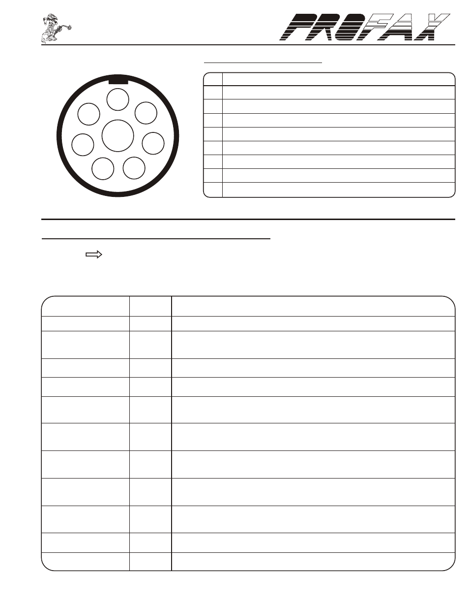
* CAUTION! - 115 VAC should not be connected to pins A & G unless the 115/24 VAC transformer option (p/n 9045) is installed.
PIN
PIN INFORMATION
A*
115 VAC power input through fuse F3 in respect to pin G
B
Voltage return from pins A or D.
C
Not used
D
24 VAC power input through fuse F2 in respect to pin G
E
Contact closure to pin F in respect to TS1 jumper on terminals 1 & 2.
F
Relay common to pins B & E in respect to TS1 jumper position.
G
Circuit common for 24 and 115 VAC input power.
H
Case ground
H
G
F
C
A
B
D
E
As viewed facing
rear of feeder.
NOTE:
Control Cords come in 10 ft., 25 ft., 50 f t. & 100 ft. lengths and consist of an 8 Socket Plug,
Multi-conductor Cord(s) and necessary Wires or Plugs to connect to the power source.
When ordering - Add the length required to the end of the part number. (Example: 9225-10)
POWER SOURCE CORD END PLUG DESCRIPTION
FOR CONNECTION TO
ST./NO.
FROM WIRE FEEDER TO:
PLUG ONLY
9046
8 Socket Plug Only - Connects to rear of wire feeder
EXTENSION CORD
9240
8 Socket Free Hanging Plug to 8 Pin Free Hanging Female Receptacle.
( Extends between the wire feeder and the interconnecting cord. )
UNIVERSAL CORD
9225
7 Individual wires
PROFAX
9237
10 Pin Plug
®
AIRCO
9234
115V Male Plug on Power Cord and 2 Prong Twistlock Female on Contactor Cord
9226
3 Prong Male Twistlock on Power Cord and 2 Prong Twistlock Female on Contactor Cord
®
HOBART
9232
115V Male Plug on Power Cord and 5 Pin Plug on Contactor Cord
9233
19 Pin Plug
®
L - TEC
9230
7 Flat Pin Male Plug (AMP Style)
9231
19 Pin Plug
®
LINCOLN
9228
5 Individual Wires with Spade Connectors for Terminal Strip Hookup
9229
14 Pin Plug
®
MILLER
9226
3 Prong Male Twistlock on Power Cord and 2 Prong Twistlock Female on Contactor Cord
9227
14 Pin Plug
®
POWCON
9235
14 Pin Plug (only power sources w/115 VAC available at plug.)
®
THERMAL DYNAMICS
9227
14 Pin Plug