Posiflex PD-300R User Manual
Page 6
Part 6
4.
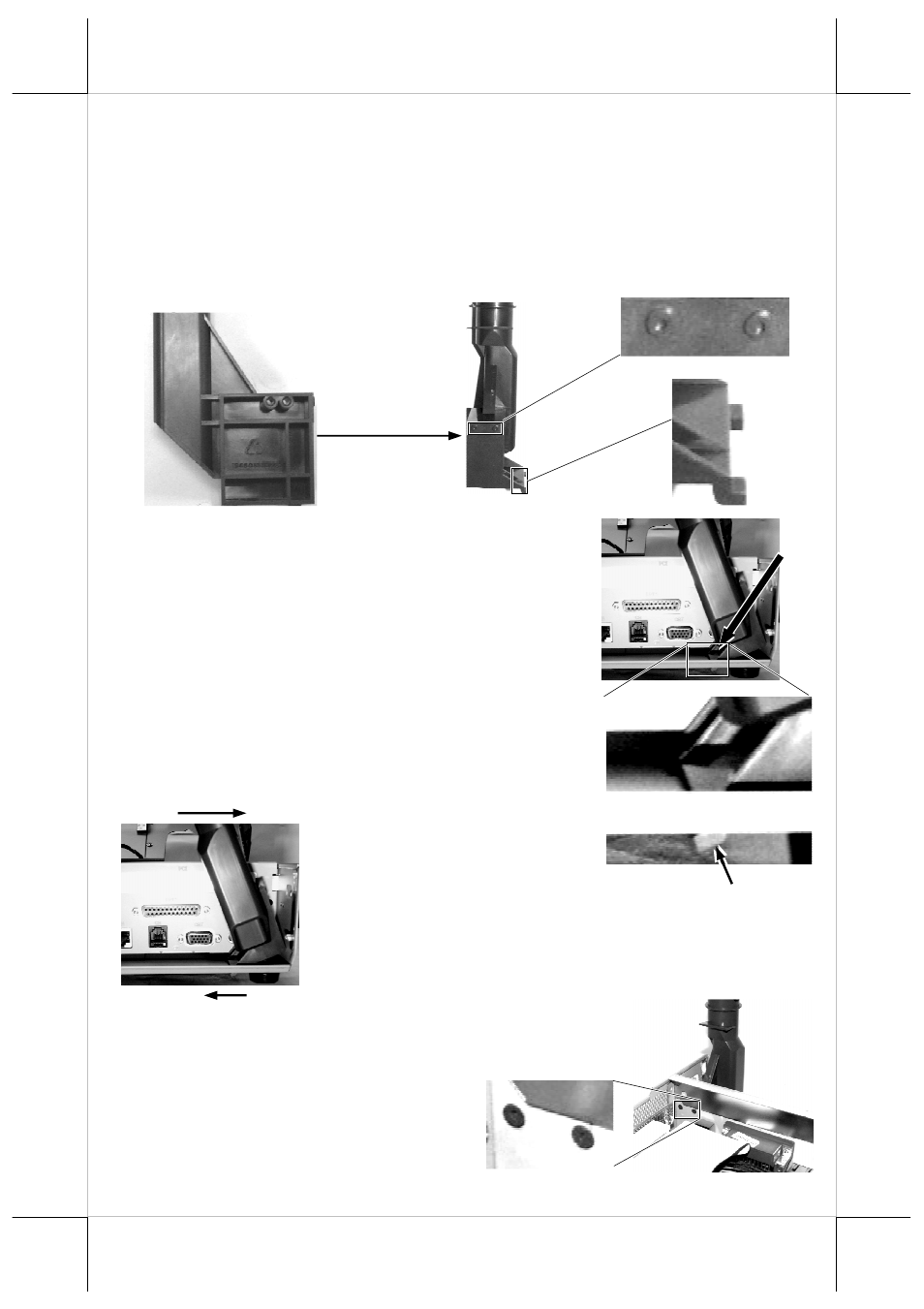
Please then refer to the pictures below for the base unit (lowest part) of
PD-307 / PD-307U with 2 enlarged portions to the right and a slightly
enlarged side view picture to the left to find 2 bottom locking lugs A’; 2
short cylindrical locating bosses B’ to fit into I/O plate; and 2 plastic
screw bosses C’ on side. Please note that the PD cable comes out of the
bottom end of the base tube yet in the illustration pictures the cable is
eliminated for sake of minimum visual confusion.
5.
Turn the pole display base unit opposite to have
the bottom locking lugs A’ facing left and now
insert the 2 bottom locking lugs A’ on base unit
into the 2 rectangular installation holes A on
bottom of HT or PB chassis from the right
corner with the pole display slightly inclined to
the left as in the upper picture at right. Please
note that both bottom locking lugs A’ should be
completely inserted and come out of the bottom
plate of HT or PB system as emphasized by an
arrow in the enlarged portion in lower right.
6.
Please always keep a
gentle pressure at the
bottom end of pole base (bottom locking lugs A’)
to the left (away from the sidewall of system
chassis) when moving the upper part of pole
toward sidewall as in the left picture.
7.
Please refer to the right
picture taken from inside of HT or PB system to
show that the 2 short cylindrical locating bosses B’
should match into 2 round holes B
in the I/O plate. The bosses B’
inside holes B are show in the
enlarged portion.
B+B’
B+B’
A’
A’
A’
B’
B’
C’ C’
A
A’